IEC 60068-2-2 & MIL-STD-810H Standards
 Unmanned Aerial Vehicles (UAVs) and commercial drones operate in compact, enclosed carbon-fiber or plastic airframes with limited natural airflow. During operation, internal heat from high-current brushless motors, lithium-polymer batteries, central processing units, and high-frequency Electronic Speed Controller (ESC) power stages builds up rapidly. In hot ambient environments or direct solar exposure, internal airframe temperatures can easily exceed 70°C to 85°C.
Under severe thermal stress, drone electronics exhibit distinct failure modes: flight controllers suffer IMU sensor bias drift and processor resets; ESCs experience MOSFET thermal shutdown or phase current imbalance; and camera gimbals suffer image sensor noise, lens defocusing, and motor holding errors.
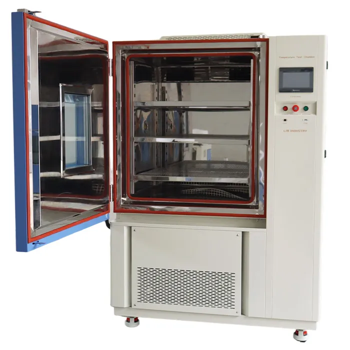
To eliminate field crashes and ensure mission reliability, engineering teams perform accelerated dry heat testing inside a Dry Heat Test Chamber. This guide details thermal degradation physics across critical drone sub-assemblies, international qualification standards (IEC 60068-2-2, MIL-STD-810H, RTCA DO-160G), test execution workflows, and turnkey equipment solutions from LIB Industry.
Different drone sub-assemblies generate and react to heat in unique ways. Evaluating drone reliability requires component-specific instrumentation, electrical loading, and diagnostic monitoring.
Sub-Assembly | Primary Heat Source | Key Thermal Risk |
Flight Controller (FC) | CPU processing heat | IMU sensor drift |
Electronic Speed Controller (ESC) | High-frequency MOSFET switching | High phase currents (30A – 120A+) |
Camera & Optical Gimbal | Sensor self-heating, enclosed housing | Dark current noise, lens focus shift, gimbal motor drift/holding error |
Flight controllers integrate micro-electro-mechanical systems (MEMS) gyroscopes and accelerometers (IMU), microcontrollers (MCU), voltage regulators, and barometric pressure sensors.
• Sensor Bias Shift: Rising temperatures cause thermal expansion in MEMS structures, creating zero-rate output shifts (g-bias and gyro drift) that lead to altitude or attitude loss in autonomous flight.
• Processor & Regulator Instability: Elevated temperatures increase thermal noise in low-dropout (LDO) regulators and trigger CPU thermal throttling or watchdog resets, causing total loss of control mid-flight.
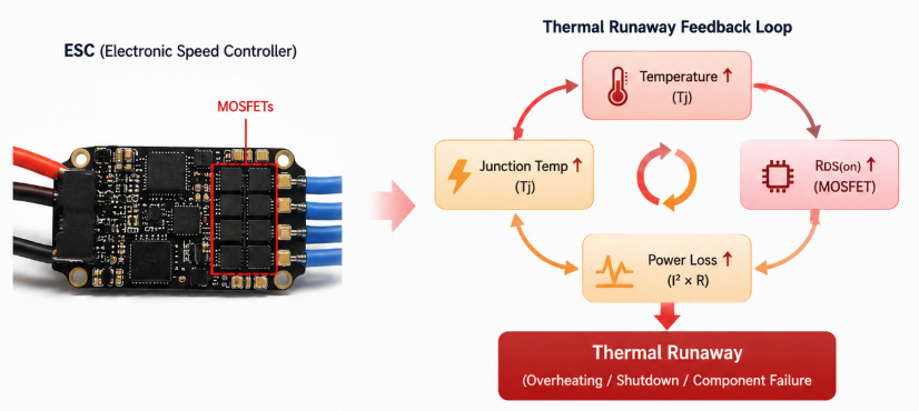
ESCs convert DC battery power into 3-phase AC driving signals for brushless motors via high-frequency pulse-width modulation (PWM).
• Switching Losses & Thermal Runaway: MOSFET internal resistance (RDS(on)) increases proportionally with junction temperature Tj:
RDS(on)(Tj) = RDS(on)(25°C) × [1 + α × (Tj − 25°C)]
Where α is the positive temperature coefficient of silicon. As Tj rises, RDS(on) increases, driving up conduction power loss (Ploss = I2phase × RDS(on)) and triggering thermal runaway, solder reflow, or premature thermal shutdown.
• CMOS Image Sensor Dark Current Noise: Sensor leakage current doubles approximately every 6°C to 8°C temperature rise, generating fixed-pattern noise, hot pixels, and frame drops.
• Lens Defocusing: Thermal expansion of composite lens barrels shifts optical element spacing, degrading image sharpness.
• Gimbal Motor Holding Error: Elevated temperatures alter motor winding resistance, causing driver thermal protection to trip or reducing stabilizing torque.
Component Assembly | Primary Thermal Stressor | Physical Failure Mechanism | Diagnostic Metric |
Flight Controller | CPU heat dissipation & ambient airframe temperature | MEMS IMU bias shift, MCU watchdog reset, LDO noise | Attitude output stability, loop timing, voltage ripple |
Electronic Speed Controller | High-current switching (I2R) & thermal buildup | MOSFET thermal runaway, phase imbalance, solder fatigue | Phase current balance, switching temp (Tj), protection trip |
Camera Module | Sensor self-heating & enclosed housing | CMOS dark current increase, lens focus shift | Frame loss, image signal-to-noise ratio (SNR), focus MTF |
3-Axis Gimbal | Motor driver heating & continuous stabilization load | Winding resistance rise, driver thermal shutdown | Holding error (degrees), motor current draw, drift rate |
Selecting the correct standard depends on whether the drone assembly is a commercial component, airborne civil aviation system, or military UAV.
Standard | Scope | Typical Temperatures |
IEC 60068-2-2 | General Commercial & Industrial | Preferred: +55°C, +70°C, +85°C |
MIL-STD-810H Method 501.7 | Tailored Military & Defense UAVs | Basic Hot (A2) / Hot Dry (A1) |
RTCA DO-160G Section 4 | Civil Airborne Equipment Environmental Qualification | +55°C, +70°C, +85°C |
• Test Method: Evaluates non-heat-dissipating (Test Bb) and heat-dissipating (Test Bd/Be) specimens under powered or unpowered conditions.
• Key Temperatures: +55°C, +70°C, +85°C, +100°C, and +125°C.
• Ramp Rate Limit: Temperature rate of change must not exceed 1 K/min (averaged over ≤5 min) to prevent unwanted thermal shock.
• Procedure I (Storage): Evaluates structural integrity and material survival under high storage temperatures (up to +71°C for Hot Dry A1 climate) for a minimum of seven 24-hour diurnal cycles.
• Procedure II (Operation): Evaluates performance while powered under peak operating temperatures (+32°C to +49°C ambient, or higher induced airframe temperatures up to +71°C) for at least three 24-hour operational cycles.
• Ramp Rate Limit: Maximum heating rate limited to 3°C/min.
Standard / Protocol | Focus Area | Temperature Range | Exposure Duration | Key Parameters & Ramp Limits |
IEC 60068-2-2 | Commercial & Industrial Electronics | +30°C to +125°C | 2h, 16h, 72h, 96h, 168h | Rate of change ≤1 K/min; powered operational validation |
MIL-STD-810H (501.7) | Military & Industrial UAV Systems | +33°C to +71°C (Induced) | 3 to 7 Diurnal 24-hour cycles | Multi-cycle storage & operation; rate of change ≤3°C/min |
RTCA DO-160G (Sec 4) | Civil Airborne Equipment | +55°C, +70°C, +85°C | 3h (Short-time) / 2h (Operating) | Category definition sets operating high and ground survival limits |
MIL-STD-202-108 | Component Life Testing | +70°C to +150°C (±2°C) | 96h to 1,000+h | Long-duration endurance screening for discrete ICs and MOSFETs |
A structured test sequence ensures that recorded failures stem from controlled thermal stress rather than improper handling or cable interference.
1. Pre-Test Inspection & Baseline Electrical Calibration
2. Component Instrumentation (thermocouple placement & cabling)
3. Sealed Feed-Through Port Setup (power & data routing)
4. Program Controlled Thermal Ramp (≤1 K/min to ≤3°C/min)
5. Isothermal Dwell & Full Electrical Load Execution
6. Real-Time Telemetry Logging (voltage, current, IMU, video)
7. Controlled Recovery & Post-Test Visual / Functional Check
1. Instrumentation & Mounting: Attach calibrated K-type thermocouples directly to high-heat components (MCU package, MOSFET heatsink, LDO regulator, and CMOS sensor housing). Mount components on low-thermal-conductivity fixtures in representative orientations.
2. Cable Routing & Feed-Through Sealing: Route high-current power cables and high-speed data interfaces (CAN bus, UART, MIPI, HDMI) through the chamber's silicone-sealed access port. Keep DC power supplies and logging computers outside the chamber.
3. Thermal Stabilization & Dwell: Ramp chamber temperature to target setpoint (e.g., +70°C or +85°C). Begin the official dwell timer only after component internal sensors indicate thermal equilibrium (ΔT < 1°C per 15 minutes).
4. Component Pass/Fail Criteria: see table below.
Sub-Assembly | Pass Criteria | Fail Criteria |
Flight Controller | Zero MCU reboots/watchdog trips; IMU gyro bias within ±0.5°/s; loop timing jitter < 5% | Any CPU reset, corrupted telemetry, or attitude divergence |
Electronic Speed Controller | Phase current imbalance < 3%; no early thermal trip under full electrical load | MOSFET short-circuit, connector melting, thermal protection trip |
Camera & Gimbal | Zero frame drops at target bitrate; gimbal stabilization error < 0.02°; focus MTF retained | Video feed loss, image noise exceedance, gimbal motor loss of torque |
Choosing the right dry heat chamber configuration depends on specimen size, total thermal dissipation, cable port requirements, and desired ramp rates.
Benchtop / Compact Chamber (50L – 225L) | Reach-In / High-Capacity (500L – 1000L) |
R&D testing of single FCs, ESCs, and camera modules. Small footprint for electronics. | Full drone airframe testing. Batch testing of multiple ESCs. High power-dissipation loads. |
Selection Parameter | Compact Benchtop Dry Heat Chamber | High-Capacity Reach-In Test Chamber |
Internal Volume | 50 Liters to 225 Liters | 500 Liters to 1,000+ Liters |
Target Test Specimen | Discrete FC boards, single ESCs, camera modules | Complete multirotor airframes, large 3-phase ESC arrays |
Temperature Range | Ambient +10°C to +150°C (or −20°C/−40°C to +150°C) | −70°C to +150°C |
Temperature Fluctuation | ±0.5°C | ±0.5°C |
Heating Ramp Rate | 3.0°C/min | 3.0°C/min to 5.0°C/min |
Access Port Diameter | Standard 50 mm silicone port | Dual 50 mm / 100 mm customizable ports |
Shelf Load Rating | 30 kg per shelf | 100 kg heavy-duty shelf layer |
Selecting high-precision environmental testing equipment requires an experienced manufacturing partner capable of delivering customized technical support.
Established in 2009, Xi'an LIB Environmental Simulation Industry is a specialized designer, manufacturer, and global provider of environmental test chambers, serving clients across 56+ countries. LIB delivers complete turnkey testing solutions—from initial laboratory space planning and custom feed-through engineering to delivery, installation, operator training, and calibration.
• Comprehensive Product Range: LIB engineers dry heat chambers, temperature/humidity test chambers, thermal shock systems, dust/water ingress equipment, and walk-in environmental test rooms.
• Pre-Delivery Quality Assurance: Completed chambers undergo a rigorous 72-hour continuous operating and multi-point calibration process prior to dispatch.
• Industry-Leading Support: All LIB systems include a 3-Year Complete Warranty and Lifetime Technical Support & Service.
|
|
|
| |
| Robust Workroom | Cable Hole | Temperature and Humidity Sensor | PID controller |
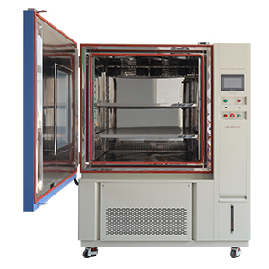
LIB TR Series High-Temperature & Dry Heat Test Chambers are tailored for electronics qualification:
• High-Precision Temperature Control: Nichrome core heating elements paired with forced-air circulation systems maintain temperature fluctuation within ±0.5°C and spatial deviation within ±2.0°C.
• Customizable Cable Feed-Through Ports: Standard 50 mm (or optional 100 mm / 150 mm) ports equipped with soft silicone plugs allow seamless passage of high-current power leads and high-frequency communication cables.
• Programmable Touchscreen PLC: Intelligent 7-inch color touchscreen controller supports multi-step temperature programs, real-time trend plotting, Ethernet/USB data logging, and automated safety alarms.
• Comprehensive Safety Protections: Built-in over-temperature cut-offs, phase-reversal protection, current leakage breakers, and external emergency-stop interlocks ensure safe, long-duration powered testing.
A leading industrial commercial drone manufacturer experienced sporadic flight controller resets and camera video telemetry dropping when conducting surveillance flights in high-temperature desert conditions (>45°C ambient).
LIB Industry custom-engineered and installed a TR-500 Dry Heat Test Chamber (500L) featuring dual 100 mm cable feed-through ports, specialized non-conductive mounting fixtures, and continuous data logging capabilities.
1. On-Site Delivery & Position Alignment in UAV R&D Lab
2. Facility Power Integration & Calibration of Thermal Sensors
3. Execution of Custom IEC 60068-2-2 & DO-160G +70°C Operational Test
4. Hands-on Training for Test Engineers on PLC Automation & Exports
5. Final Sign-off & 3-Year Warranty Activation
By powering the flight controller, camera gimbal, and 80A ESCs under full load at +70°C inside the LIB chamber, engineers identified localized thermal saturation on an internal LDO regulator (>115°C junction temperature). The manufacturer redesigned the airframe heatsink path, eliminating field resets prior to mass production.
"LIB's dry heat chamber and custom cable ports allowed us to isolate a critical thermal regulator flaw in our flight controller before full commercial launch. The temperature stability and data logging interface made compliance verification effortless." |
To support complete drone environmental qualification—from thermal stress to humidity, thermal shock, and vibration—LIB Industry offers a portfolio of complementary environmental test equipment:
Equipment Series | Core Qualification Function | Applicable Standards | Ideal Test Specimen |
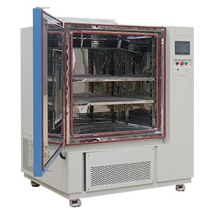
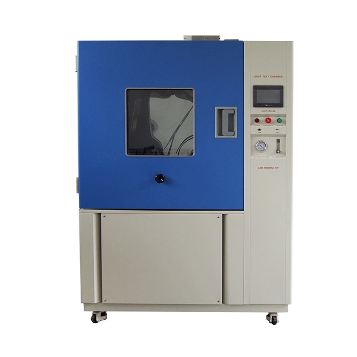
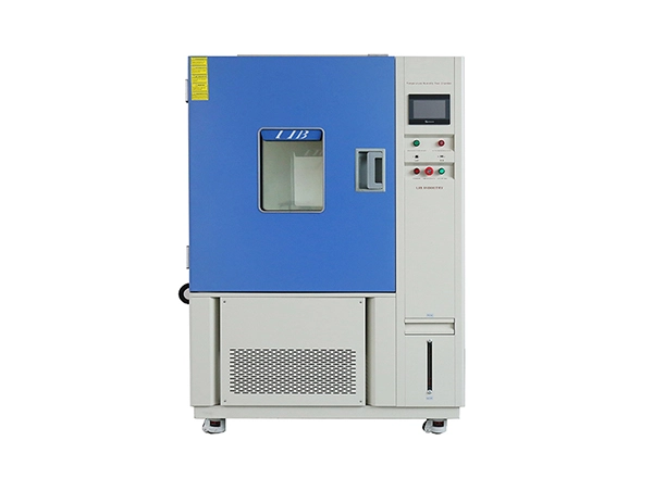
| High-temperature operational & storage screening | IEC 60068-2-2, MIL-STD-810H 501.7 | Flight controllers, ESCs, camera gimbals |
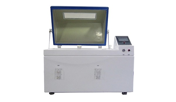
| Combined thermal and moisture cycling | IEC 60068-2-30, MIL-STD-810H 507.6 | Conformal coated PCBs, telemetry modules |
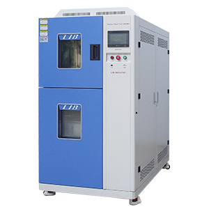
Rapid thermal expansion & stress fatigue | MIL-STD-883 Method 1010, JESD22-A104 | Surface-mount ICs, solder joints, power stages | |
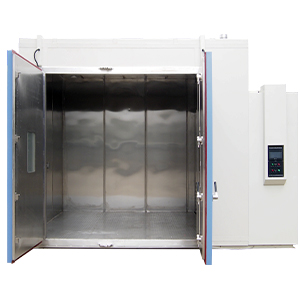
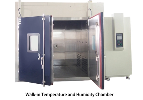
| Utility-scale airframe thermal testing | RTCA DO-160G, Custom OEM Profiles | Complete UAV platforms, large-batch components |
Q1: What temperature should drone flight controllers and ESCs be tested at?
Standard commercial drone electronics are typically tested at +55°C to +70°C for operational qualification, and up to +85°C for high-temperature storage or extreme airframe screening. Always refer to component manufacturer datasheets and target flight profiles.
Q2: Can an ESC be safely powered under full electrical load inside a dry heat chamber?
Yes. Powered ESC testing requires routing DC power and control wires through a sealed cable access port to external power supplies and load banks. Emergency power cut-off interlocks and over-temperature safety limits must be active during testing.
Q3: How do you measure flight controller thermal drift during a dry heat test?
Mount the flight controller on a fixed, vibration-isolated rig inside the chamber. Connect telemetry output to an external computer and continuously log MEMS gyroscope/accelerometer raw outputs, attitude estimations, MCU loop timing, and supply rail voltages across the thermal ramp and dwell.
Q4: Why is a dry heat chamber preferred over a humidity chamber for initial high-temperature testing?
Dry heat testing isolates purely thermal failure modes—such as semiconductor thermal runaway, solder reflow, and sensor bias drift—without introducing moisture condensation variables, making root-cause analysis simpler during early R&D phases.
Accelerated dry heat testing is essential for discovering electronic flaws before they lead to costly field failures and drone crashes. Partnering with LIB Industry ensures access to precise environmental chambers, customizable feed-through engineering, and reliable long-term support.
Contact LIB Industry today to speak with an environmental testing specialist, request technical datasheets, or receive a customized quotation tailored to your drone qualification program.
Email: inquiry@libtestchamber.com
Services Provided: Free Technical Consultation, Custom Access Port Engineering, On-Site Installation, Certified Calibration, 3-Year Warranty, Lifetime Technical Support.
 English
 русский
 français
 العربية
 Deutsch
 Español
 한국어
한국어 italiano
 tiếng việt
 ไทย
ไทย Indonesia