_20260622142635.webp) Automotive ECUs rarely fail because a component simply becomes too hot or too cold. The greater challenge is repeated temperature change. Cold starts, engine compartment heat, charging cycles, power switching, and environmental swings all cause continuous expansion and contraction between the different materials inside an ECU.
Automotive ECUs rarely fail because a component simply becomes too hot or too cold. The greater challenge is repeated temperature change. Cold starts, engine compartment heat, charging cycles, power switching, and environmental swings all cause continuous expansion and contraction between the different materials inside an ECU.
Solder joints, PCB laminates, semiconductor packages, connectors, and housings each have different coefficients of thermal expansion (CTE). After thousands of cycles, accumulated mechanical stress can lead to solder fatigue, intermittent electrical faults, communication errors, or complete failure.
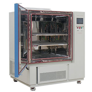
A JESD22-A104 Temperature Cycling Chamber recreates this stress under controlled conditions, helping manufacturers catch reliability risks before vehicle validation and mass production. This requires accurate temperature control, stable cycling performance, sufficient heat load capacity, and the ability to monitor powered ECUs during the test.
Not sure which chamber configuration fits your ECU program? Talk to a LIB test engineer — we'll help you match temperature range, heat load, and cable interfaces to your qualification plan, free of charge.
A JESD22-A104 Temperature Cycling Chamber is an environmental test chamber designed to evaluate electronic components and assemblies under repeated high and low temperature exposure.
The JESD22-A104 standard, developed by JEDEC, focuses on temperature cycling testing for semiconductor devices, packages, and solder interconnections. In automotive applications, the method is widely used for:
Automotive ECUs
PCB assemblies
Electronic control modules
Semiconductor packages
Solder joint reliability evaluation
Unlike simple temperature storage tests, temperature cycling creates mechanical stress by repeatedly changing the temperature between defined extremes. This reveals hidden weaknesses that may not appear during normal functional testing.
For example, an ECU may pass a room-temperature inspection but develop intermittent CAN communication failures when exposed to repeated thermal cycling. JESD22-A104 testing helps reproduce these conditions and connect failures with temperature-related stress.
Modern automotive electronics combine multiple materials with different thermal expansion characteristics, including:
Copper circuits
FR-4 PCB materials
Silicon semiconductor packages
Solder alloys
Aluminum housings
Polymer seals and adhesives
When temperature changes repeatedly, these materials expand and contract at different rates. The resulting mechanical stress concentrates in vulnerable areas such as solder joints, BGA corners, connector pins, and component mounting points.
For example, an ECU installed near an engine may experience:
Low-temperature cold starts in winter
High-temperature operation near the engine
Rapid temperature changes during vehicle operation
Heat generated by power electronics
Electric vehicles create additional thermal challenges. Battery controllers, motor controllers, and power management systems experience heat generated by switching losses, charging cycles, and cooling system changes.
Temperature cycling testing helps detect:
Solder joint fatigue
BGA cracking
PCB delamination
Connector contact resistance increase
Semiconductor package damage
Housing and sealing deformation
Many ECU failures are intermittent rather than permanent. A crack may only open at low temperature or high temperature, causing short communication interruptions, ECU resets, or diagnostic trouble codes. Thermal cycling testing makes these failures repeatable and measurable.
JESD22-A104 evaluates electronic components through repeated temperature transitions in a gaseous environment. The test profile is determined by several critical parameters:
Low temperature (Tmin)
High temperature (Tmax)
Soak time
Temperature ramp rate
Cycle count
Sample temperature (not chamber-air temperature)
The actual product temperature is more important than chamber air temperature. A properly designed test requires verification using thermocouples attached to the sample itself, not just the chamber sensor.
Common JESD22-A104.01 temperature conditions:
Condition | Low Temperature | High Temperature |
A | -55°C | +85°C |
B | -55°C | +125°C |
C | -65°C | +150°C |
G | -40°C | +125°C |
H | -55°C | +150°C |
M | -40°C | +150°C |
For solder-interconnect reliability testing, common practices include:
Controlled ramp rates, typically ≤15°C/min (10–14°C/min preferred)
Soak Modes 1–4, requiring minimum dwell of 1/5/10/15 minutes at each extreme
1–2 cycles/hour for solder work, with cycle times under 30 minutes generally avoided
Accurate sample temperature monitoring, not just chamber air
Dual-chamber load transfer completed in under one minute
The selected condition should match the actual automotive application and the governing qualification document (JESD22-A104, AEC-Q100/Q200, ISO 16750-4, or the OEM's own LV 124-based spec). A harsher profile does not always mean better testing — excessive stress can create failures that never occur in real vehicle use, wasting time chasing a non-issue.
A reliable ECU thermal cycling test should be designed around the product application, installation environment, and expected failure mechanisms. A generic temperature profile may not accurately represent real vehicle conditions.
Before testing, engineers should determine:
Minimum and maximum temperature
Number of cycles
Temperature ramp rate
Soak time
Powered or non-powered test condition
Electrical monitoring requirements
For automotive ECU qualification, profiles such as -40°C to +125°C are commonly used, but the correct condition depends on the vehicle location, component type, and OEM requirements. A powertrain ECU, battery management system, and cabin electronics module may each require different conditions because their operating environments differ.
The ECU should be installed with fixtures that allow sufficient airflow around the sample. Temperature sensors should be placed at critical locations, such as:
Processor packages
Power components
PCB center areas
Connector sections
A temperature profile measured in an empty chamber does not represent the actual condition of a loaded ECU test — always verify with the real fixtures, cables, and sample mass installed.
Many automotive ECU tests require powered operation during thermal cycling. Typical monitoring includes:
Supply current
CAN / LIN / Ethernet communication
Output signals
Reset events
Resistance changes
A suitable chamber should provide sealed cable access ports to connect external monitoring equipment without compromising chamber sealing performance. Record chamber-air and product temperature separately — a loaded ECU can lag the air reading by several minutes.
After completing the test, engineers evaluate whether the ECU meets functional and structural requirements. Failure analysis may include:
Visual inspection
X-ray inspection
Cross-section / dye-and-pry analysis
Electrical performance comparison
Solder joint examination
The final report should include the test profile, sample temperature data, cycle number, electrical monitoring results, and failure conditions. This is what converts temperature cycling from a simple environmental exposure into a defensible reliability evaluation.
Selecting a JESD22-A104 chamber requires more than checking a temperature range on a datasheet. The chamber must match the ECU size, power consumption, test profile, and monitoring requirements.
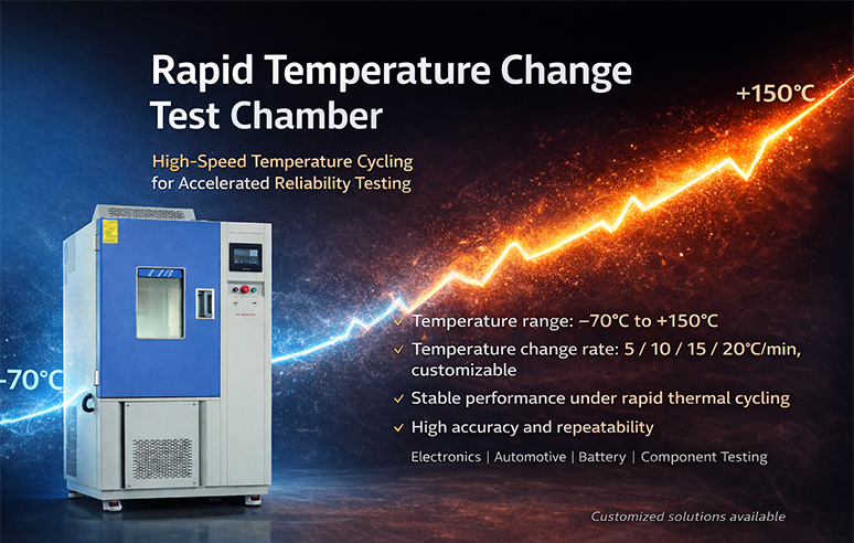
Temperature Range and Cycling Capability — Automotive electronics commonly require -40°C to +125°C, -40°C to +150°C, or, for extreme environments, down to -70°C. The chamber should hold both extremes stably while controlling the transition rate specified by the standard.
Heat Load Capacity for Powered ECU Testing — Powered ECUs generate additional heat inside the chamber. Consider the number of ECUs tested simultaneously, ECU operating power, fixture heat absorption, and cable/monitoring equipment. A chamber with insufficient heat-load capability may hit the air-temperature setpoint but still fail to bring the sample to the required temperature.
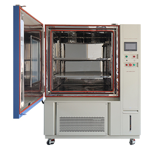
Chamber Size and Airflow Design — The workspace needs room for ECU samples, fixtures, sensors, and cable connections. More volume isn't automatically better — even airflow around the sample matters more than raw capacity.
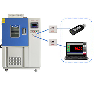
Electrical Feedthrough and Data Monitoring — A suitable chamber should support CAN, LIN, Ethernet, thermocouple, and resistance-measurement feedthroughs so engineers can monitor ECU behavior continuously across thousands of cycles.
Still comparing chamber specs across suppliers? Send us your ECU dimensions, power draw, and target standard and we'll recommend a configuration — no obligation.
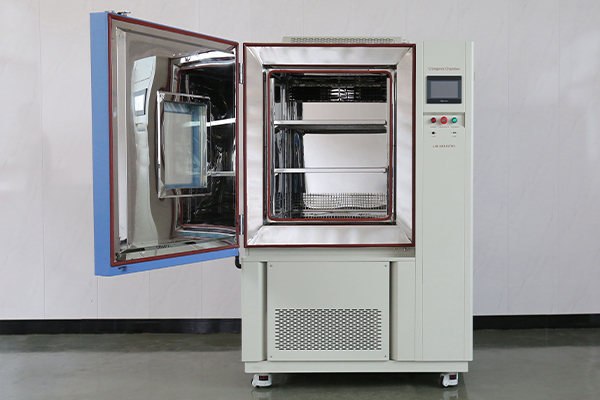
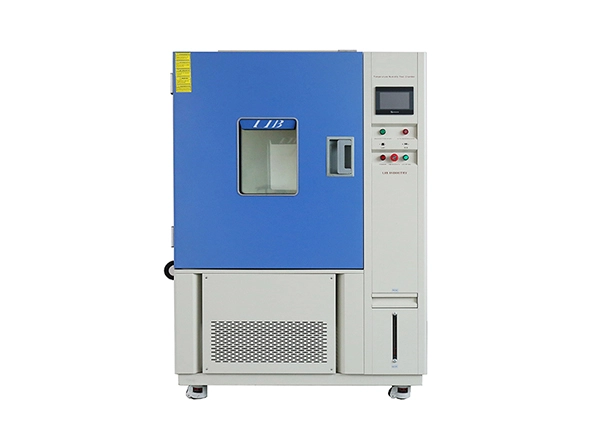
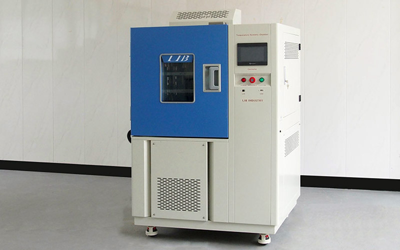
Xi'an LIB Environmental Simulation Industry has designed and manufactured environmental test chambers since 2009, with equipment deployed across automotive electronics, semiconductor, and PCB reliability labs. LIB chambers for ECU testing are configurable for temperature range, chamber size, heat load, cable access, and monitoring systems, and support:
JESD22-A104 temperature cycling testing
Automotive ECU reliability validation
Electronic component qualification
PCB thermal stress testing
Environmental durability evaluation
Key specifications:
| Parameter | Specification |
|---|---|
| Temperature Range | -20°C to +150°C / -40°C to +150°C / -70°C to +150°C |
| Heating & Cooling Rate | 10°C/min standard; 15°C/min configuration available |
| Temperature Fluctuation | ±0.5°C |
| Temperature Deviation | ±2.0°C |
| Workspace Capacity | 100 L – 1,000 L |
| Rated Heat Load | 1,000 W |
| Controller | Programmable touchscreen |
| Communication | Ethernet / USB |
| Interior Material | SUS304 stainless steel |
| Refrigeration | Mechanical compression system |
| Maximum Noise | 65 dBA |
 | |
|
|
|
| Robust Workroom | Cable Hole | Rom |
Automotive reliability testing often runs into hundreds or thousands of cycles over weeks of continuous operation. LIB chambers are built for stable long-duration cycling with programmable profiles, automatic cycle operation, data recording, forced-air circulation, and custom test fixtures. For powered ECU testing, sealed cable ports allow connection to external monitoring systems without breaking chamber performance.
Different automotive components need different test setups. LIB customizes chambers based on ECU dimensions, sample quantity, heat generation, cable interfaces, fixture design, and special temperature profiles — so you're not forced to adapt your test plan to a fixed off-the-shelf box.
Request a custom quote → Tell us your ECU type, target standard (JESD22-A104 / AEC-Q100 / ISO 16750-4 / LV 124), and sample quantity, and our engineers will propose a chamber configuration within 1 business day.
ECU qualification rarely stops at temperature cycling. Manufacturers typically pair it with other environmental tests to validate complete product reliability. LIB supplies the full range:
Temperature & Humidity Chamber — climate durability and humidity resistance testing for automotive electronics across storage, transport, and operating conditions. |
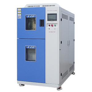
— faster two-zone or three-zone temperature transitions for material compatibility and solder/package stress analysis, complementing JESD22-A104 cycling. |
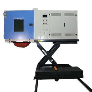
— mechanical vibration and transportation simulation, often combined with thermal cycling for combined-environment ECU validation. |
— for JESD22-A104 and IEC 60068-2-14 change-of-temperature testing on components and assemblies. |
Browse LIB's full test chamber lineup → or contact us for a combined thermal + vibration test plan for a single ECU program.
A JESD22-A104 Temperature Cycling Chamber helps automotive manufacturers identify hidden reliability risks caused by repeated thermal stress. For ECU applications, accurate product-temperature control, controlled ramp rates, sufficient heat-load capability, and electrical monitoring are essential for meaningful results.
Chamber selection should start with ECU size, operating power, temperature range, cycle requirements, monitoring connections, and the applicable qualification standard — not just a temperature range on a spec sheet.
By combining reliable temperature control with application-focused configuration, LIB temperature cycling chambers help automotive electronics manufacturers improve product durability and reduce unexpected failures during vehicle validation and production.
What Is a JESD22-A104 Temperature Cycling Chamber Used For?It is used to evaluate components, PCB assemblies, solder joints, and automotive electronic systems under repeated high and low temperature changes to identify thermal fatigue failures before vehicle validation.
How Is Temperature Cycling Different from Thermal Shock Testing?Temperature cycling controls transition rates and dwell times to simulate repeated environmental changes. Thermal shock uses much faster transitions between zones, creating stronger thermal gradients and a different failure mechanism.
Can ECU Testing Be Performed While Powered?Yes. Powered ECU thermal cycling can monitor CAN, LIN, and Ethernet communication, current consumption, outputs, and reset events, provided the chamber has sealed cable access and proper safety controls.
How Do I Select the Right Temperature Cycling Chamber?Consider ECU size, sample quantity, heat generation, required temperature range, cycle count, electrical monitoring needs, and the applicable standard.
What Warranty Does LIB Provide on Its Temperature Cycling Chambers?Every LIB chamber, including JESD22-A104 configurations for automotive ECU testing, comes with a standard 36-month (3-year) warranty covering the refrigeration system, controller, and core components — well beyond the 12-month warranty common at many competitors, reflecting confidence in the durability of the SUS304 test space and mechanical compression system.
Does LIB Only Make Temperature Cycling Chambers?No. Beyond JESD22-A104 temperature cycling chambers, LIB manufactures a full range of environmental test equipment, including temperature & humidity chambers, thermal shock chambers, vibration test systems, altitude/low-pressure chambers, and salt spray/corrosion test chambers — allowing automotive electronics manufacturers to source a complete reliability test lab from a single supplier.
Send us your ECU dimensions, target temperature range, cycle count, and qualification standard (JESD22-A104, AEC-Q100, ISO 16750-4, or LV 124), and LIB's engineers will propose a chamber configuration and quote — typically within 1 business day.
[Request a Quote] | [Talk to an Engineer] | [Download Chamber Datasheet]
 English
 русский
 français
 العربية
 Deutsch
 Español
 한국어
한국어 italiano
 tiếng việt
 ไทย
ไทย Indonesia