Electronic assemblies work in environments with rapidly changing conditions. Factory floors experience fast temperature shifts, and tropical outdoor locations add more challenges. PCBs and electronic systems face daily moisture problems. Temperature humidity chamber electronics testing reproduces these real conditions well before products ship. It simulates real-world humidity and temperature cycles inside a controlled space, allowing engineers to detect condensation, dew point issues, and false failures that might otherwise go unnoticed. This article explains why moisture is a major challenge for electronics, how PCB condensation testing can go wrong, and what chamber practices reduce errors and build confidence in product reliability.
Humidity directly affects electronics. Water vapor turns into liquid when air temperature falls below the dew point. On a populated circuit board, this liquid can create bridges between conductors, causing leakage currents, corrosion, and short-term faults. Rapid hot-cold or dry-moist cycles in a chamber amplify these risks.

For example, a test raising temperature to 85°C with 85% relative humidity may produce condensation when cooling if dew point isn’t controlled. Even if parts pass later cycles, brief condensation can stress interfaces, weaken insulation resistance, and create hidden defects. PCB condensation tests can thus produce misleading failures, often caused more by chamber control than by product design.
Dew point is the temperature at which air becomes saturated and liquid forms. Chamber air at 85% relative humidity and 35°C has a dew point near 29°C. If the temperature drops below this point, condensation forms when air and surfaces meet.
Standard PCB humidity tests often use daily temperature swings, start-stop cycles, or long soaks to check moisture balance. Without strong dew point control, uneven airflow or air pockets can cause some parts to reach dew point sooner, leading to surface condensation first in corners, recessed areas, and high-thermal-mass components.
If dew point isn’t properly managed, moisture can remain on surfaces even after relative humidity drops. Engineers may misattribute erratic leakage currents or insulation dropouts to design flaws, when simple condensation is the real cause. Proper chamber settings can prevent this entirely.
In a PCB humidity testing chamber, not every failure is the same. Some common false positives appear often. They can mislead teams if the chamber setup is not right.
Humidity creates thin layers of conductive film on insulating surfaces. During a test, a sudden drop in insulation resistance may look like a real design defect. But it can reverse fully once the moisture dries up.
A thin film of water can bridge two close nets on a board. This creates an intermittent short. In systems with wide operating tolerances, it may seem like a serious fault. Yet no permanent damage exists.
Moisture left on solder masks or around component pins speeds up oxidation that is easy to see. This can worry product teams. But the build would survive normal field exposures without issue.
These problems get worse when chamber control systems cross the dew point too far or fail to slow ramp rates. Fluctuating humidity pockets make some sections of a sample wetter than others. This leads to inconsistent results across boards that are exactly the same.

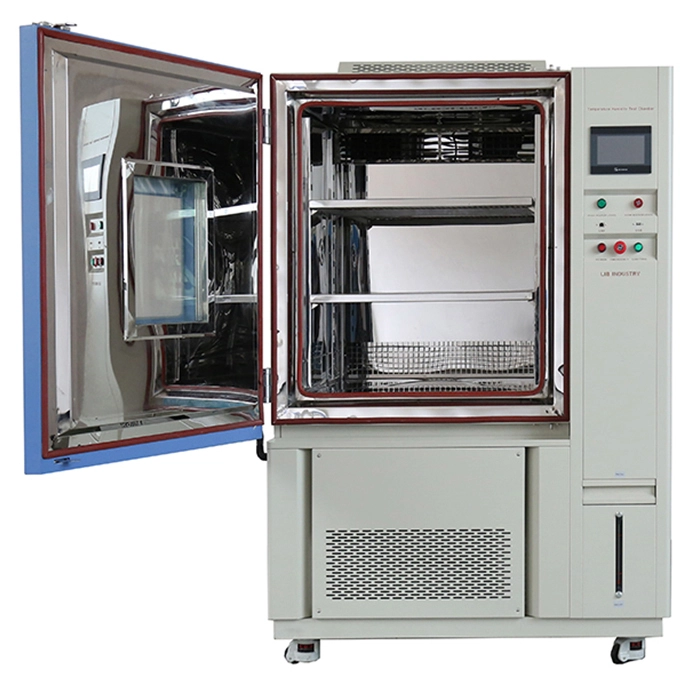
Temperature and humidity chambers built for electronics testing use several smart control strategies. These strategies lower condensation risks during PCB testing. The right setup makes a big difference.
Model | TH-100 | TH-225 | TH-500 | TH-1000 |
Interior Volume | 100L | 225L | 500L | 1000L |
Temperature Range | A : -20℃ ~ +150 ℃ B : -40℃ ~ +150 ℃ C: -70℃ ~ +150 ℃ | |||
Temperature Fluctuation | ± 0.5 ℃ | |||
Temperature Deviation | ± 2.0 ℃ | |||
Humidity Range | 20% ~ 98% RH | |||
Humidity Deviation | ± 2.5% RH | |||
Cooling Rate | 1 ℃ / min | |||
Heating Rate | 3 ℃ / min | |||
Controller | Programmable color LCD touch screen controller,PC Link, LAN interface for remote control | |||
Interior Material | SUS304 stainless steel | |||
Chambers with fine sensors and quick feedback loops hold target conditions more steadily than basic timers. Tight control stops overshooting humidity setpoints. This keeps dew point transitions steady and easy to predict.
Sudden changes in temperature or humidity raise the chance of moisture drops. A well-set chamber slows ramp up and ramp down. This lets air and surfaces stay close to balance and cuts condensation.
Even heat and moisture spread matter a lot. Non-uniform airflow creates pockets where dew point is crossed too soon. Chambers with calibrated circulation patterns fix this issue and keep everything even.
Continuous logs of temperature, humidity, and calculated dew point let teams link failures to exact environmental events. This clear view separates true design weaknesses from test environment artifacts.
By using these approaches together, electronics teams can trust that a failure in a temperature humidity test really shows the product’s behavior. It does not come from test setup quirks.
Good chamber controls are only one part of success. How a test is prepared and run also affects how accurate the results are. Smart steps before and during the test make everything better.
Moisture trapped in internal layers and components acts differently from surface humidity. Pre-conditioning boards in steady ambient conditions before testing makes moisture content uniform and easy to predict.
Every time a chamber door opens, normal lab air breaks the test profile. This can cause short-term condensation, especially near the door seal area. Good planning cuts down unnecessary openings and keeps conditions stable.
Running the same profile on dummy boards or reference samples helps spot whether moisture issues repeat or tie to specific design features. If leakage currents spike only on one design run, the problem likely sits in the sample and not in chamber control.
Heavy assemblies with metal shields or large heatsinks take in or give off heat more slowly than thin boards. Adjusting ramp rates to fit this thermal mass helps the whole sample reach target conditions at the same even pace.
Experienced labs create profiles that match field conditions closely. They do not just use default chamber presets. These custom profiles cut false positives and uncover real failure modes that matter.
Picking the right temperature and humidity chamber means looking at more than just size and cost. Engineers and lab managers should check several key points to make sure the chamber fits their needs.
|
|
Choose chambers that hold relative humidity and temperature with very little change. Small ups and downs can push conditions past the dew point without warning.
A bigger chamber may look more flexible at first. But smaller benchtop units often give more even air circulation for small boards. Match the size to usual sample batches instead of planning only for future needs.
Modern chambers include built-in data systems. The power to export time-stamped logs of humidity, temperature, and calculated dew point makes troubleshooting and compliance reports much easier.
Chambers last for many years as important equipment. Vendors that offer fast calibration, spare parts, and training help labs keep testing valid over a long time.
Manufacturers provide many different setups. The most important factor is matching test goals to chamber abilities, especially for dew point control and moisture risk reduction.
Xi’an LIB Environmental Simulation Industry has earned a strong name for giving solid temperature humidity chamber solutions. These solutions fit electronics and PCB testing needs well. With decades of work in environmental test equipment, LIB offers products that mix exact control with simple daily use.
LIB’s chambers use accurate sensors and steady control systems that meet the strict demands of the electronics industry. Engineers who want to check designs against humidity-related failures gain from custom profiles and real-time monitoring during every test.
Beyond the hardware, LIB gives customers full service choices. These include help with installation, calibration support, and advice on applications. This wide support lets testing teams build profiles that match real-world conditions. It also helps them read results with full confidence. Whether in a product development lab, quality assurance area, or manufacturing checkpoint, LIB’s solutions let users find moisture-related issues early and in a dependable way.
A temperature humidity chamber electronics test puts circuit boards into a set environment. There, temperature and relative humidity change to copy real-world conditions. This kind of testing helps find moisture-related failures early while products are still in the lab.
Dew point humidity chamber control makes sure air and board surfaces do not cross key moisture points too fast. By handling the link between humidity, temperature, and dew point, it cuts condensation formation. This leads to test outcomes that teams can trust more.
Common signs include quick drops in insulation resistance. Intermittent short circuits appear when the chamber cools. Oxidized surfaces show up around component leads. If these happen at exact dew point changes, they often point to moisture condensation instead of design defects.
Yes, well-planned PCB condensation testing can speed up moisture stress and show possible long-term failures such as corrosion or delamination. The main point is to keep controlled humidity profiles that match expected field conditions.
Review chamber profiles first. Make sure dew point calculations stay accurate. Check ramp rates next. Verify uniform airflow too. Sometimes the apparent failures link back to how conditions were applied and not to the board design itself.


 English
 русский
 français
 العربية
 Deutsch
 Español
 한국어
한국어 italiano
 tiếng việt
 ไทย
ไทย Indonesia