Corrosion testing for electronics is rarely about rust alone. A connector can still look acceptable and fail on contact resistance. A plated shield can pass a visual check and still lose long-term reliability in the field. That is why uniform salt deposition matters so much in a salt spray corrosion test chamber. When salt fog falls unevenly, one specimen may get a light mist while another gets pooling, runoff, or direct spray. The result is not a fair comparison. It is a distorted one.
For a salt spray corrosion test chamber, the real job is simple: create a stable fog, let it settle naturally, and keep that fallout rate within the range required by the test method. ASTM B117, ISO 9227, and IEC 60068-2-11 all treat spray collection, solution chemistry, temperature, and specimen placement as core controls, not side details.、
Uniform salt deposition means the salt mist reaches the exposure zone as a fine, stable fallout rather than as wet bursts, nozzle streaks, or edge-heavy condensation. In practice, the chamber is not judged only by whether it “makes fog.” It is judged by whether the collected spray volume, concentration, and pH stay within the standard range at different points near the specimens.
A fallout rate of 1 to 2 mL per hour per 80 cm² sounds like a simple operating value. It is not. That number is the checkpoint that tells a lab whether the chamber is producing the right corrosive load across the working area. ASTM B117 requires at least two collectors per atomizer tower, positioned near the specimens, one close to a nozzle and one far from it. ISO 9227 and IEC 60068-2-11 also require at least two collecting devices to check chamber homogeneity.
A good corrosion test lets engineers compare like with like. That only happens when each sample sees roughly the same salt fog climate. If one connector row is shadowed and another faces heavy fallout, the result says more about rack layout than coating quality. For that reason, the standards call for free circulation of mist, prevention of drip from one specimen onto another, and specimen placement that avoids direct impingement.
Large steel panels can hide a lot. High-precision electronic components cannot. A tiny plated spring contact, a crimp terminal, or a PCB edge connector may fail after very limited corrosion growth.
On a small electronic part, a pore, pinhole, scratch, or thin plating area is enough to shift the result. One corner with excess deposit can trigger early white rust. One blocked airflow path can leave another part underexposed. This is why electronics labs care about uniform salt fog coverage more than dramatic chamber output. A violent spray may look active, but it makes weak data.
IEC 60068-2-11 is written for electrotechnical products, components, equipment, and materials. It also calls for visual checks and, where relevant, electrical and mechanical checks before and after the test. That fits electronics reality. A relay pin, RF can, sensor terminal, or chip package leadframe may be rejected because function drifts, not because corrosion looks severe from a distance.
Most deposition problems come from a few practical issues. They are usually visible in the chamber long before they appear in a test report.
Nozzle condition matters. So does atomizing pressure. So does how the chamber handles airflow after the mist is generated. ISO 9227 says the cabinet must meet homogeneity and distribution conditions, the spray must not hit specimens directly, and baffles or a dispersion tower may be used to improve distribution. IEC 60068-2-11 adds that the chamber should be vented in a way that prevents pressure build-up and supports uniform salt mist distribution.
Loading is where many repeatability problems start. ASTM B117 places specimens between 15° and 30° from vertical unless otherwise specified. IEC 60068-2-11 uses normal operating position where relevant, and otherwise 20° ± 5° to the vertical is the default. Both standards also say specimens should not touch each other, should not touch the chamber, and should not allow runoff onto lower samples.
Common cause | What it does to the test | What to check |
Nozzle scaling or partial blockage | Raises local fallout, creates wet streaks | Collector readings, nozzle cleaning, solution filtration |
Poor baffling or unstable airflow | Makes one side of the chamber harsher | Near/far collector comparison |
Overloaded rack | Creates shadowing and drip paths | Sample spacing and free circulation |
Wrong specimen angle | Causes pooling or underexposure | Fixture angle against the method |
Unstable solution level or chemistry | Changes fog density and pH | Reservoir control, pH, concentration logs |
Repeatability is what makes salt spray data useful. Without it, a chamber becomes a fog generator, not a test instrument.
When salt deposition stays stable, batch-to-batch comparison gets cleaner. A lab can compare plating thickness changes, pretreatment shifts, or supplier lots with more confidence. IEC 60068-2-11 even requires a trial run of at least 24 hours before testing when needed, and recommends checking collection rate with the chamber loaded similarly to the real test. That is a practical reminder: an empty chamber and a filled chamber do not behave the same way.
Uniform fallout reduces false pass and false fail calls. If collector data, pH, salt concentration, and chamber temperature all stay inside the method window, it is easier to say the result came from the specimen, not from chamber drift. It is also easier to defend the report during customer audits or internal release reviews. ASTM B117 and ISO 9227 are comparative lab methods, not direct calendar-life predictors, so disciplined repeatability is what gives them value.
These three standards overlap on the basics, but each one matters for a slightly different reason. ASTM B117 is the classic continuous salt fog method. ISO 9227 broadens that framework to NSS, AASS, and CASS. IEC 60068-2-11 is especially relevant for electrical and electronic products, where post-test functional checks often matter as much as surface appearance.
Standard | Application | Key Requirements Affecting Uniform Salt Deposition |
ASTM B117 | Corrosion testing for coatings and metallic materials | 35 ± 2 °C exposure temperature; 5 ± 1% NaCl solution; collected pH 6.5–7.2; deposition rate 1.0–2.0 mL/80 cm²·h (≥16 h average); specimen angle 15°–30°; minimum 2 collectors (near/far) to verify distribution |
ISO 9227 | NSS, AASS, CASS testing for industrial materials | NSS: 50 ± 5 g/L NaCl; pH 6.5–7.2 (NSS), pH 3.1–3.3 (AASS/CASS); 35 °C (NSS/AASS), 50 °C (CASS); 1–2 mL/80 cm²·h collection rate; chamber must ensure uniform fog distribution and homogeneity |
IEC 60068-2-11 | Electrical and electronic components and assemblies | 35 ± 2 °C; 50 ± 5 g/L NaCl; pH 6.5–7.2; deposition rate 1.5 ± 0.5 mL/80 cm²·h; specimen angle 20° ± 5°; ≥24 h stabilization when required; test durations from 16–672 h |
Good salt spray work is usually boring in the best sense. The chamber is steady. The logs are clean. The collector readings are predictable.
A practical routine looks like this:
· Pre-condition the chamber before loading production samples.
· Verify fallout using at least two collectors placed near the exposure zone.
· Keep specimen angles consistent with the chosen standard.
· Leave space between parts so mist can circulate freely.
· Prevent one sample from dripping onto another.
· Filter solution when needed and keep the reservoir stable.
· Record temperature, pH, concentration, and collection rate on schedule.
· Match the chamber load during setup to the real test load whenever possible.
For electronics work, a chamber needs more than nominal compliance. It needs stable control, clean sample positioning, and practical ways to check fallout.
 | ||||
| Model | S-150 | S-250 | S-750 | S-010 |
Interior Volume (L) | 110 | 320 | 410 | 780 |
Temperature Range | Ambient ~ +60 ℃ | |||
Humidity Range | 95% ~ 98% RH | |||
Salt Fog Deposition | 1~2ml / 80cm2 · h | |||
Spray Type | Continuous / Periodic | |||
Salt Fog Collected | Fog collector and fog measure cylinder | |||
Air Preheating | Saturated air barrel | |||
Spraying System | Atomizer tower and Spray nozzles | |||
Controller | PID controller | |||
Safety Device | Humidifier Dry-combustion Protection; Over-temperature Protection; Over-current Protection; Water Shortage Protection; Earth leakage Protection | |||
Material | Glass fiber reinforced plastics | |||
Standard Configuration | 6 round bars and 5 V-shaped grooves | |||
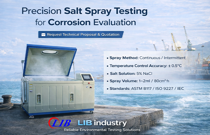
LIB’s salt spray corrosion test chamber is built around the controls that matter for repeatable test results: 95% to 98% RH, salt fog deposition in the 1–2 mL/80 cm²·h range, continuous or periodic spray modes, atomizer tower and spray nozzles, a saturated air barrel, and PID control with real-time monitoring. The chamber body uses glass fiber reinforced plastics, and the one-piece molded design helps resist salt attack while making cleanup easier after long exposure runs.
That setup is a good fit for high-precision electronic components because the working area supports angled placement instead of crowding parts flat on a shelf. Standard round bars and V-shaped grooves allow flexible positioning, and customized holders are available for irregular samples. That helps when testing PCB coupons, connectors, terminals, sensor housings, miniature plated parts, and other small assemblies where free circulation and drip control are critical. LIB also serves electronics as one of its target industries.
Xi’an LIB Environmental Simulation Industry has been manufacturing and supplying environmental test chambers since 2009, covering design, production, sales, and service for global customers. Its product range goes beyond corrosion chambers to include climate, weathering, dust, water ingress, and other environmental simulation systems. The company states that its products have passed CE and RoHS-related certifications, and its service support includes installation, commissioning, training, maintenance guidance, repair support, a 36-month warranty, and lifelong follow-up service. For buyers building or upgrading a corrosion lab, that matters almost as much as chamber specifications. A stable machine is important. Stable support after delivery is just as important.
Uniform salt deposition is the difference between a chamber that only creates fog and a chamber that produces data a lab can trust. For high-precision electronic components, that difference shows up fast. Small parts react to slight shifts in fallout, airflow, positioning, and drainage. When the chamber holds a stable salt mist climate and the operator follows the standard closely, repeatable test results become much easier to achieve. That is what turns salt spray testing into a useful decision tool for electronics quality, supplier approval, and product reliability.
Because corrosion results must come from the sample, not from chamber imbalance. Uniform salt deposition makes comparison fair, reduces local overexposure, and improves repeatable test results. ASTM B117, ISO 9227, and IEC 60068-2-11 all require collectors and controlled operating conditions for that reason.
The usual causes are nozzle blockage, unstable solution feed, weak baffling, bad venting, overloaded racks, and poor specimen positioning. Any of these can create direct spray, shadowing, or runoff from one specimen to another.
IEC 60068-2-11 is the most directly relevant standard when testing electrotechnical products and components. ASTM B117 and ISO 9227 are also widely used for coatings, housings, terminals, and metal parts used in electronics, depending on the product specification and customer requirement.
Yes, if the test method, specimen setup, and acceptance criteria are defined correctly. In electronics, the evaluation often includes visual, electrical, and mechanical checks, not appearance alone. That is especially important for connectors, plated leads, and functional contact surfaces.
Start with chamber mapping and collector checks. Then keep the solution chemistry stable, maintain the correct specimen angle, avoid crowding, match the chamber load during setup to the real test load, and log temperature, pH, concentration, and fallout consistently. Those steps do more for repeatable test results than simply increasing spray intensity.

 English
 русский
 français
 العربية
 Deutsch
 Español
 한국어
한국어 italiano
 tiếng việt
 ไทย
ไทย Indonesia