Relative humidity looks simple on a display, but accurate RH sensor calibration is not simple at all. A small error in humidity sensor accuracy can affect pharmaceutical storage, cleanroom monitoring, electronics testing, battery labs, material conditioning, and production quality records. A sensor reading 55%RH when the real condition is 60%RH may seem harmless in an office. In a controlled warehouse, laboratory, or environmental test process, that gap can lead to wrong decisions.
A humidity calibration chamber gives RH sensors a stable, repeatable, and documented calibration environment. Instead of relying on open-room air or a single fixed humidity point, it creates controlled temperature and humidity conditions across a wider operating range. For teams that need routine RH sensor calibration, incoming inspection, production testing, or in-house quality control, the chamber becomes the controlled space where readings can be compared with a traceable reference standard.
RH readings are strongly tied to temperature, airflow, sensor placement, water vapor distribution, and stabilization time. Without a controlled environment, even a good reference sensor may not give useful comparison data.

A normal laboratory room changes every minute. Doors open. Air conditioning cycles. Operators move around. Equipment gives off heat. A sensor placed near a wall, vent, lamp, or power supply can read differently from a sensor in the center of the room.
This is why uncontrolled room calibration often creates scattered data. One sensor may respond faster than another. A capacitive RH sensor may lag after a step change. A probe with a protective filter may need more time to settle. When the environment itself keeps moving, it becomes difficult to separate real sensor error from room fluctuation.
Saturated salt solutions are widely used for relative humidity calibration. ASTM E104 describes a method for generating constant RH environments in relatively small containers, with application from dryness to near saturation at 0°C to 50°C, including hygrometer calibration. It also states that saturated salt solutions can be corrosive and that temperature control of about ±0.1°C is needed to realize generated RH values within about ±0.5%RH.
Fixed-point values can be precise, but they are limited. They are usually small-volume, static setups. They may not match the airflow, chamber loading, cable routing, or multi-sensor comparison needed in industrial RH sensor calibration. For example, common saturated salt values at 25°C include about 32.78%RH for magnesium chloride, 57.57%RH for sodium bromide, and 75.29%RH for sodium chloride, each with its own uncertainty.
Calibration approach | Typical strength | Main limitation |
Ambient room comparison | Fast and low cost | Room RH and temperature are unstable |
Saturated salt fixed point | Useful known RH points | Small closed systems, corrosive salts, slower workflow |
Humidity calibration chamber | Wide RH range, repeatable programs, multi-sensor loading | Requires chamber selection, reference standard, and procedure control |
A humidity calibration chamber does not replace a reference standard. It creates the controlled condition where the device under test and the reference standard can be compared fairly.
 Stable Humidity Control Reduces Calibration Uncertainty
During relative humidity calibration, the chamber is set to target points such as 30%RH, 50%RH, 75%RH, or 90%RH. Once the set point is stable, the reference instrument and DUT readings are recorded at the same time.
This controlled method reduces common sources of calibration error: drifting room air, short-term HVAC changes, operator heat, poor sealing, and uneven moisture distribution. It is especially helpful for batch calibration, where ten, twenty, or more RH sensors must be compared under the same condition.
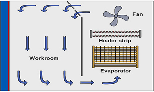
Good chamber airflow matters. Sensors near the chamber wall, door, or humidifier outlet should not see a different condition from sensors in the center. A chamber with internal fan and air duct design helps distribute temperature and humidity more evenly, reducing local deviation between positions. LIB’s humidity calibration chamber is designed with internal airflow distribution and chamber insulation to support stable humidity control.
Relative humidity is temperature-dependent. At the same water vapor content, a warmer air mass shows a lower RH reading, while a cooler air mass shows a higher RH reading. That is why RH sensor calibration should not treat humidity alone as the only variable.
For example, a 25°C and 50%RH calibration point is not the same practical condition as 40°C and 50%RH. Sensors used in electronics aging rooms, greenhouse controls, automotive interiors, or pharmaceutical stability rooms may need multi-point checks at both humidity and temperature set points.
IEC 60068-3-4 gives guidance for damp heat testing and chamber operation. It notes that high humidity combined with elevated temperature creates stress on products, and it gives chamber operation details such as using water conductivity between 5 µS/cm and 20 µS/cm at +23°C, cleaning internal chamber parts before testing, and avoiding direct water injection into the working space.
A good humidity calibration chamber still needs a careful procedure. Poor loading, rushed readings, and wrong reference placement can damage the value of the calibration result.

The reference standard should be placed close to the DUT sensing area, not beside the chamber wall or directly in the airflow outlet. If multiple probes are loaded, they should have enough spacing for air movement. Cable holes should be sealed after wiring to reduce leakage.
A common sequence is to move from low RH to high RH: 30%RH, 50%RH, 75%RH, then 90%RH. This lowers condensation risk on sensors, filters, and housings. When high humidity testing is needed, operators should pay attention to dew point and avoid quick temperature drops that may cause water to form on the sensor surface.
RH sensors need time to settle. A bare sensor may stabilize faster than a probe with a sintered filter, protective cap, or plastic enclosure. In production calibration, a fixed soak time should be written into the procedure. For example, after chamber stability is reached, a team may wait 20 to 40 minutes before recording data, depending on sensor construction and required uncertainty.
The usual workflow is simple:
· Set the chamber humidity and temperature point.
· Wait until the reference standard and DUT readings are stable.
· Record chamber set point, reference reading, DUT reading, time, and serial number.
· Calculate the correction value or pass/fail result.
· Repeat at all required humidity points.
For high-value calibration records, raw readings should be saved rather than only writing “pass.” A sensor may pass today but show drift later, and trend data helps maintenance teams plan recalibration.
Humidity errors are not only laboratory problems. They show up in storage rooms, production lines, climate chambers, and field monitoring systems.
Calibration labs need repeatable relative humidity calibration points, traceable reference instruments, and clear records. In-house quality teams use a humidity calibration chamber to check incoming RH probes, production batches, repaired sensors, and field-returned devices before reuse.
Pharmaceutical warehouses, cleanrooms, and stability areas often work within defined RH windows. If a room monitor drifts low, a real humidity excursion may be missed. If it drifts high, the site may investigate a false alarm. Accurate RH sensor calibration helps keep environmental records credible.
Electronics labs use RH sensors to track moisture exposure during PCB, connector, battery, and coating tests. Automotive test teams monitor humidity during interior material, sensor module, and control unit validation. In environmental testing, RH sensors support damp heat tests where both temperature and humidity affect electrical leakage, corrosion, swelling, and insulation resistance.
The right chamber is not always the largest or the most complex. It should match the sensor range, workload, uncertainty target, and daily operating method.
If sensors are used between 30%RH and 80%RH, the chamber should cover those points with room at both ends. If sensors are used in high-humidity aging, storage, or damp heat environments, coverage up to 90%RH or above is useful. A 20%RH to 98%RH chamber range gives broad coverage for most industrial RH sensor calibration work.
Look beyond the RH range. Temperature fluctuation, temperature deviation, chamber sealing, airflow layout, humidification method, and water quality all affect repeatability. For sensor calibration, stable air around the DUT matters more than a wide specification that cannot be held under load.
A small batch of handheld hygrometers may need a compact chamber. A production line checking dozens of transmitters may need more volume, shelves, cable holes, and fixture space. Operators should leave enough spacing around each sensing head instead of filling the chamber like a storage cabinet.
Programmable steps, network connection, alarms, and data export reduce manual work. These features are useful when running multi-point calibration overnight or when one technician must manage several chambers and reference instruments.
A practical humidity calibration chamber should cover common calibration points, keep stable humidity, allow enough room for sensor loading, and support repeatable programs.
LIB humidity calibration chamber covers 20%RH to 98%RH, which fits many RH sensor calibration routines from low-humidity storage checks to high-humidity environmental monitoring. It can be set to fixed humidity points or cyclic humidity changes for different calibration needs.
The chamber’s humidity deviation is controlled at ±2.5%RH. For calibration work, this figure should be read correctly: the chamber creates a stable comparison environment, while the reference standard determines the calibration correction. A lower and repeatable deviation helps operators judge sensor drift more clearly across repeated runs.
LIB offers chamber volumes from 100L to 1000L, giving laboratories and production teams room to match the chamber size with sensor quantity, fixture design, cable routing, and test workload. Larger volumes are useful when probes, transmitters, data loggers, and display units need to be checked together.
A programmable color LCD touch screen controller and Ethernet connection help teams run step programs, record data, and manage long calibration routines. The chamber also uses automatic water supply, a water purification system, stainless steel interior, cable port, shelves, viewing window, and safety protection for humidity system, over-temperature, over-current, water shortage, and leakage risks.
Key chamber parameter | Practical value for RH sensor calibration |  |
Humidity range | 20%RH to 98%RH | |
Humidity deviation | ±2.5%RH | |
Temperature options | Low-temperature options down to -20°C, -40°C, or -70°C; upper range to +150°C | |
Temperature fluctuation | ±0.5°C | |
Temperature deviation | ±2.0°C | |
Interior volume | 100L, 225L, 500L, 800L, 1000L | |
Heating / cooling rate | 3°C/min heating, 1°C/min cooling | |
Control | Programmable touch screen, Ethernet connection |
Xi’an LIB Environmental Simulation Industry manufactures environmental test chambers for global customers, with design, production, sales, installation, training, and after-sales service as part of its test chamber supply capability. LIB has worked in environmental test chamber manufacturing since 2009, serves customers worldwide, and supplies product lines covering temperature and climate chambers, corrosion chambers, dust and water IP chambers, weathering chambers, and special test chambers.
For RH sensor calibration users, LIB’s value is not only the chamber hardware. Stable humidity control, stainless steel workroom design, automatic water supply, chamber insulation, safety protection, and programmable control all support daily calibration work. The chamber can be used for fixed humidity calibration points or cyclic humidity programs. Calibration equipment must stay usable after delivery. LIB provides installation, commissioning, maintenance guidance, training, a 36-month warranty, lifelong follow-up service, and support from after-sales and local service teams.
A humidity calibration chamber is used to create stable relative humidity and temperature conditions for RH sensor calibration, hygrometer checking, transmitter comparison, and humidity data logger verification.
RH sensor calibration keeps humidity readings reliable. It helps detect sensor drift, reduce false alarms, support quality records, and protect materials or products that are sensitive to moisture.
Many facilities calibrate RH sensors every 6 to 12 months. Sensors used in high humidity, chemical vapor, cleanroom monitoring, pharmaceutical storage, or critical testing may need shorter intervals based on drift history and internal quality rules.
A practical RH sensor calibration range often includes points such as 30%RH, 50%RH, 75%RH, and 90%RH. A chamber range from 20%RH to 98%RH covers most common laboratory and industrial calibration points.
Yes. One humidity calibration chamber can calibrate multiple sensors at the same time when the chamber has enough volume, good airflow, proper spacing, sealed cable access, and a stable reference standard placed near the sensing area.


 English
 русский
 français
 العربية
 Deutsch
 Español
 한국어
한국어 italiano
 tiếng việt
 ไทย
ไทย Indonesia