 Carbon Capture, Utilization, and Storage (CCUS) technologies require permanent, scalable mineralization pathways to convert captured carbon dioxide into stable products. In concrete research, CO2 carbonation curing offers a dual benefit: it permanently sequesters carbon dioxide as solid calcium carbonate minerals while enhancing early mechanical strength, refining pore structure, and reducing water absorption in cementitious binders, recycled concrete aggregates (RCA), and industrial by-products like steel slag.
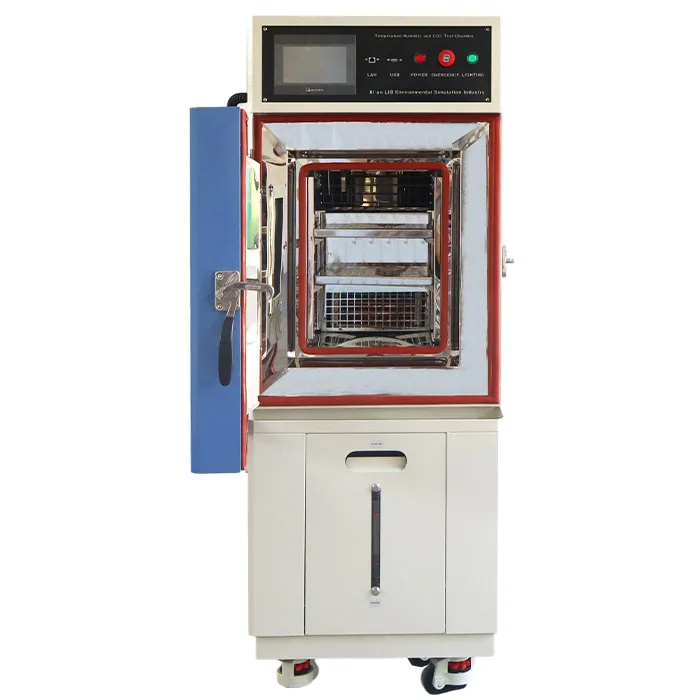
Bridging the gap between a promising chemical reaction and a scalable manufacturing process requires precise laboratory control. A dedicated CO2 Carbonation Curing Chamber provides the monitored, repeatable environment needed to evaluate binder formulations, optimize gas diffusion, and accurately quantify carbon uptake.
This comprehensive guide breaks down the chemical mechanisms, critical environmental parameters, testing standards (EN 12390-12, ISO 1920-12, RILEM CPC-18R1), experimental workflows, and turnkey equipment solutions from LIB Industry.
To design meaningful CCUS experiments, researchers must distinguish managed early-age carbonation curing from passive natural weathering.
Natural Carbonation | CO2 Accelerated Curing |
Passive, ambient exposure | Managed, early-age treatment |
Low CO2 concentration (~0.04%) | High CO2 concentration (1% to 20%) |
Takes months to years | Takes minutes to 72 hours |
Lowers pH, risks rebar rust in reinforced concrete | Densifies matrix, boosts early strength & sequesters CO2 |
Natural carbonation occurs passively as atmospheric CO2 (~0.04%) diffuses into hardened concrete over months or years. It reacts with hydration products, lowering the pore solution pH from above 12.5 to below 9.0. In reinforced concrete, this loss of alkalinity depassivates the embedded steel, making natural carbonation a durability concern for mature structures.
Carbonation curing is an intentional, early-stage manufacturing process applied to fresh, demolded, or preconditioned cementitious materials. By exposing the matrix to elevated CO2 concentrations under controlled relative humidity and temperature, carbon dioxide rapidly dissolves into the pore water to form solid carbonate minerals.
Key Takeaway Carbonation curing results should never be directly substituted for service-life durability predictions without validated correlation models, as early-stage mineralization intentionally alters the initial microstructural evolution of the material. |
Carbonation curing converts gaseous carbon dioxide into solid mineral phases via aqueous dissolution and precipitation reactions:
Ca(OH)2 + CO2 →(H2O)→ CaCO3 + H2O
C-S-H + x CO2 →(H2O)→ C-S-H (calcium-depleted) + x CaCO3 + y H2O
Additional pathways occur when treating magnesium- or iron-bearing materials, such as steel slag compacts and alternative low-clinker binders.
Parameter | Target Range | Why It Matters |
Moisture Balance | 50% – 70% RH | Too dry: no aqueous film for CO2 dissolution. Too wet: pores fill with water, blocking gas diffusion. |
Temperature Control | 20°C – 40°C | Regulates gas solubility and mineral precipitation rates. |
CO2 Concentration & Gas Circulation | Process-dependent | Drives the concentration gradient without localized stagnation. |
Parameter / Protocol | Research & Screening Ranges | EN 12390-12 Standard | ISO 1920-12 Standard |
Primary Objective | Process optimization & CO2 uptake screening | Carbonation resistance comparison | Carbonation depth profiling for concrete classes |
CO2 Concentration | 1% to 20% by volume | 3.0% ± 0.5% | 3.0% ± 0.5% |
Temperature | 20°C to 40°C | 20°C ± 2°C | 22°C ± 2°C (Hot climate: 27°C ± 2°C) |
Relative Humidity | 50% to 70% RH | 57% ± 3% RH | 55% ± 5% RH (Hot climate: 65% ± 5% RH) |
Exposure Duration | Minutes to 72 hours | 28 days curing + 14 days conditioning | Variable cycling intervals |
Primary Endpoint | Pmax gain, uptake (g CO2/kg), pore refinement | Carbonation depth (dk) via indicator spray | Comparative carbonation front tracking |
A disciplined laboratory workflow prevents preconditioning variations or chamber loading effects from distorting carbonation performance data.
1. Define Objective & Prepare Replicates (≥3 samples per group)
2. Record Initial Baseline (mix ratio, green density, dry mass)
3. Standardize Pre-Conditioning (equal RH/moisture loss)
4. Program Chamber & Execute Curing (CO2, temperature, RH, gas flow)
5. Continuous Monitoring & In-Situ Data Logging
6. Post-Curing Characterization (uptake, depth, strength, XRD)
Specimen Spacing & Airflow: Maintain at least 20 mm to 50 mm of clearance around every specimen inside the chamber. Dense stacking blocks gas circulation, leading to uneven carbonation fronts.
Moisture-Corrected Mass Balance: A rapid mass increase during curing does not automatically prove carbon sequestration. Mass changes must be corrected for water evaporation or condensation using Thermogravimetric Analysis (TGA) or elemental combustion analysis.
Indicator Spray Precision (RILEM CPC-18R1): When measuring carbonation depth, spray a freshly fractured surface with a 1% phenolphthalein alcohol solution. Record at least 3 to 5 depth points per edge to the nearest 0.2 mm, distinguishing the uncarbonated purple zone (pH > 10.0) from the clear carbonated zone.
Controlled carbonation curing is applied across several key structural and material pathways:
Precast Concrete Units | Steel Slag & By-Products | Recycled Aggregates |
Rapid early strength allows early demolding | Converts waste into structural carbonates | Densifies porous mortar coating |
• Precast Concrete Masonry Units (CMUs): Early-age exposure to elevated CO2 allows rapid strength development, shortening demolding cycles and reducing steam curing energy requirements.
• Steel Slag Compacts & Industrial Waste: High-calcium/magnesium slag compacts gain structural integrity as carbonates bind loose mineral particles into a matrix without relying on traditional Portland cement.
• Recycled Concrete Aggregate (RCA) Enhancement: Carbonating crushed concrete waste densifies the porous attached mortar coating, lowering water absorption and improving mechanical bonding when reused in fresh concrete mixes.
Standard environmental chambers lack the gas-tight seals, safety interlocks, and non-dispersive infrared (NDIR) control systems required for precise carbonation research.
Operating Parameter | Standard Temperature/Humidity Chamber | LIB CO2 Carbonation Curing Chamber |
CO2 Concentration Range | Ambient (~0.04% only) | 0% to 20% (controlled via NDIR sensor) |
Temperature Range | -20°C to +100°C | -60°C to +150°C (±0.5°C accuracy) |
Humidity Range | 20% to 98% RH | 10% to 98% RH (±1.0% to ±1.5% RH accuracy) |
Gas Handling System | Open venting / non-sealed | Gas-tight workspace, automated purge & pressure relief valve |
Workspace Material | Standard stainless steel | Grade SUS304 corrosion-resistant stainless steel |
Safety Interlocks | Thermal overload cut-off | Overpressure alarm, CO2 leak detection, interlocked door locks |
Selecting specialized testing equipment requires an engineering partner with proven manufacturing experience and complete turnkey support.
Established in 2009, Xi'an LIB Environmental Simulation Industry is a dedicated manufacturer and global supplier of environmental test chambers. LIB provides turnkey solutions—from custom structural design and gas integration to delivery, installation, calibration, and operator training.
• Comprehensive Testing Suite: LIB manufactures temperature/humidity chambers, CO2 carbonation test chambers, salt spray systems, weathering chambers, and custom walk-in environmental rooms.
• Quality Assurance: All LIB chambers undergo rigorous functional inspection, multi-point sensor calibration, and continuous commissioning prior to dispatch.
• Industry-Leading Warranty: All LIB equipment is backed by a 3-Year Complete Warranty and Lifetime Technical Support & Service.
| 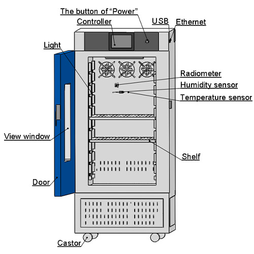 |
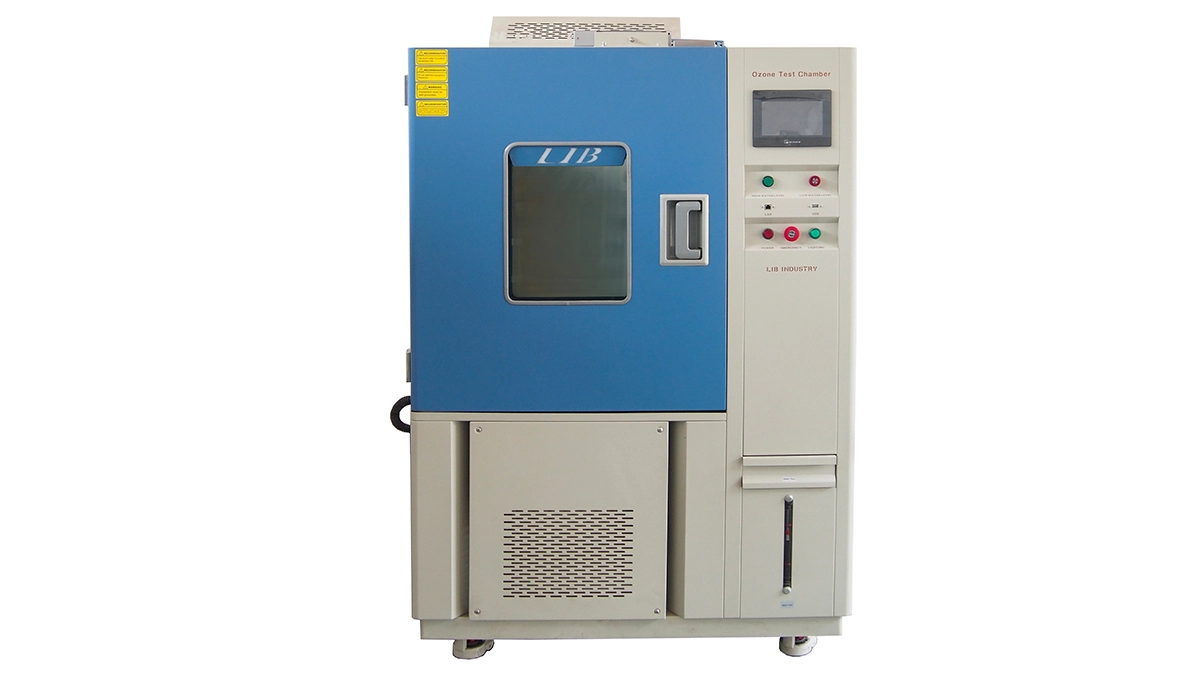
• Precision NDIR CO2 Control: Non-dispersive infrared sensors continuously monitor CO2 concentrations up to 20% without gas consumption, driving automated solenoid injection valves.
• Multi-Parameter Programmable PLC: Touchscreen interface displays real-time curves for CO2 percentage, temperature, and relative humidity, with full CSV data logging via USB and Ethernet connectivity.
• Integrated Safety Architecture: Automatic overpressure relief valves, gas leak alarms, and forced ambient air purging prior to door opening protect laboratory personnel.
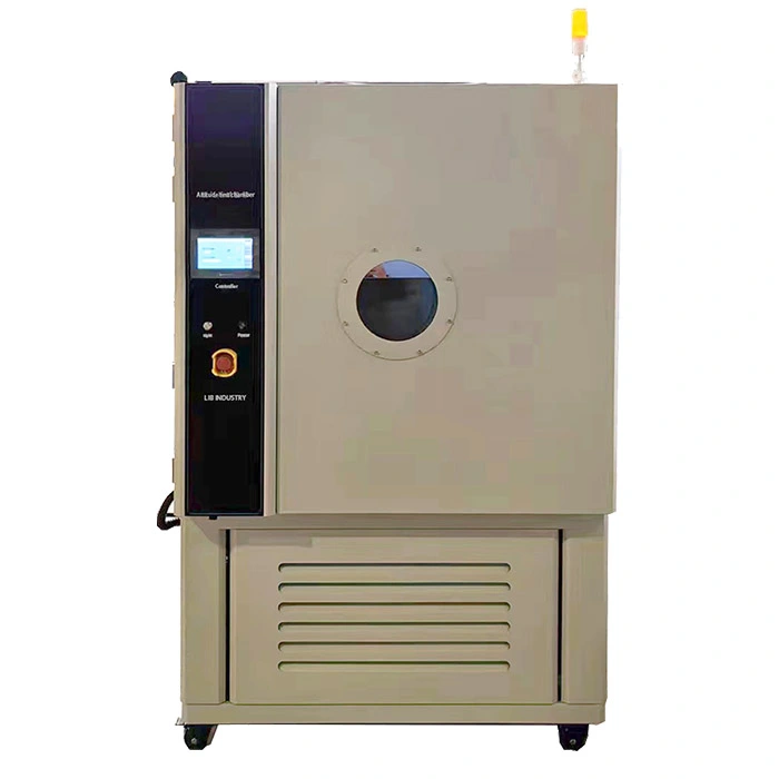
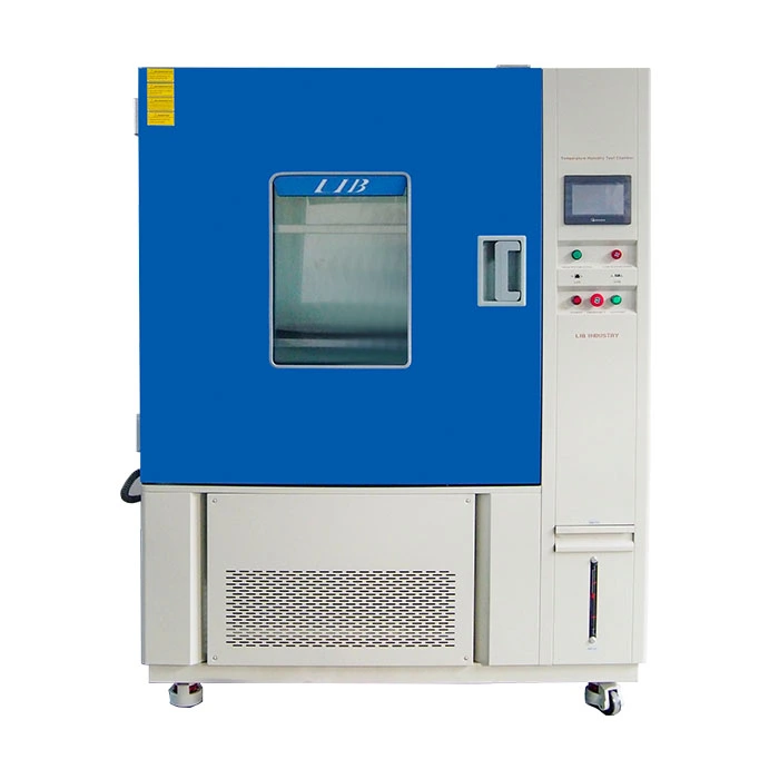
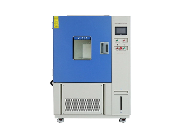
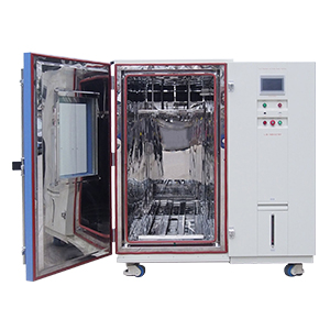
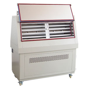
To support comprehensive CCUS research, concrete durability evaluation, and multi-factor environmental testing, LIB Industry offers a complete portfolio of complementary environmental test equipment:
Concrete Rapid Freeze-Thaw Test ChamberPrimary Application: Key Features:
| |
A university civil engineering laboratory conducting CCUS research on steel slag compacts and recycled concrete aggregates required an environmental chamber capable of executing stable 20% CO2 carbonation curing profiles while maintaining strict 60% RH and 30°C thermal control.
1. On-Site Installation & Gas Line Utility Connection
2. Gas-Tight Pressure Decay & NDIR Sensor Calibration
3. Multi-Point Temperature & Humidity Mapping across Specimen Racks
4. Hands-on Training for Research Team on Program Step Execution
5. Final Sign-off & 3-Year Warranty Activation
Using the LIB CO2 Carbonation Chamber, the research team achieved reproducible mineralized uptake rates (>8% mass gain via CO2) across steel slag compacts within 24-hour cycles. The automated data logging enabled clear correlation between chamber RH stability and carbonation front depth.
"The stability of LIB's chamber across long 72-hour carbonation cycles was crucial for our CCUS uptake modeling. The automated gas purge and safety relief features gave our team complete confidence when operating at elevated CO2 concentrations." |
Q1: What is the main difference between carbonation curing and natural carbonation?
Carbonation curing is a rapid, managed early-stage treatment (using 1% to 20% CO2) applied to fresh or demolded materials to accelerate strength gain and mineralize carbon dioxide. Natural carbonation is a slow, passive process driven by ambient air (~0.04% CO2) over years that can depassivate steel in mature reinforced concrete.
Q2: Why is humidity control critical during carbonation experiments?
Carbon dioxide must dissolve in pore water to react with calcium phases. If relative humidity is too low (<40% RH), pores dry out and the reaction stops. If humidity is too high (>80% RH), water fills the pore network, severely restricting CO2 gas diffusion. The optimal window is generally 50% to 70% RH.
Q3: How is CO2 uptake accurately measured in cured specimens?
Net uptake can be calculated via mass balance, but gravimetric data must be corrected for water loss or gain. For precise verification, researchers combine mass change with Thermogravimetric Analysis (TGA) or elemental combustion analysis to measure carbonated mineral mass directly.
Q4: Can LIB customize CO2 Carbonation Chambers for large-scale specimens?
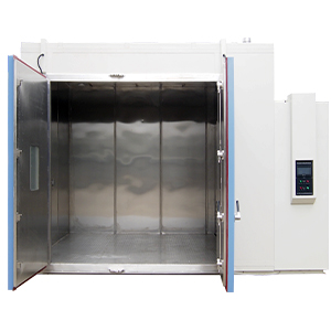
Yes. LIB offers custom workspace volumes ranging from compact benchtop units to walk-in environmental test rooms, complete with heavy-duty specimen racking, multi-zone gas injection, and customized cable/sensor access ports.
Accelerating carbonation research requires precise control over gas concentrations, thermal dynamics, and relative humidity. Partnering with LIB Industry provides your laboratory with reliable equipment, traceable data logging, and turnkey support.
Contact LIB Industry today to consult with an environmental testing specialist, receive technical datasheets, or request a custom quotation tailored to your research program.
Email: ellen@lib-industry.com
Services Provided: Free Technical Consultation, Custom Chamber Engineering, On-Site Installation, Certified Calibration, 3-Year Warranty, Lifetime Technical Support.
 English
 русский
 français
 العربية
 Deutsch
 Español
 한국어
한국어 italiano
 tiếng việt
 ไทย
ไทย Indonesia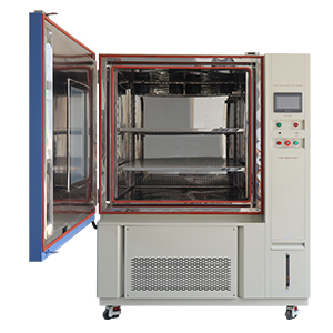

.webp "Combined Environmental Salt Spray Chamber")