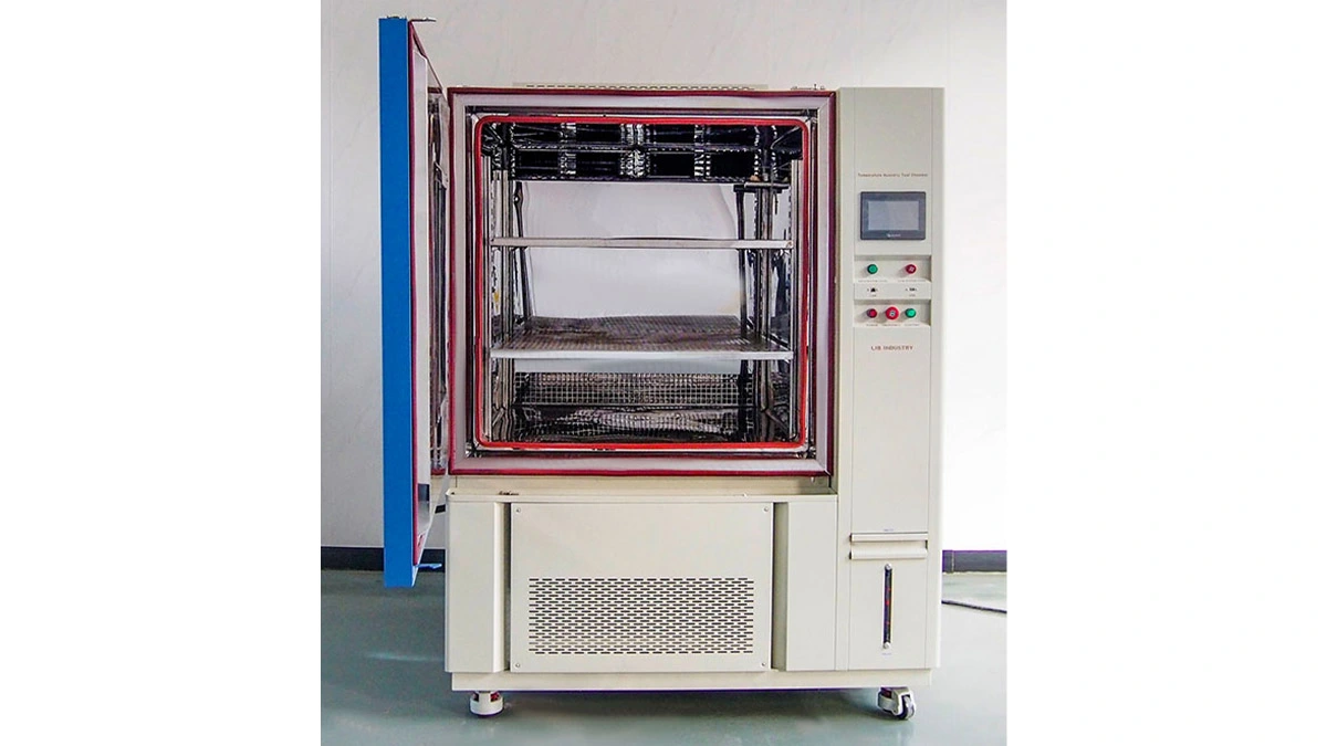
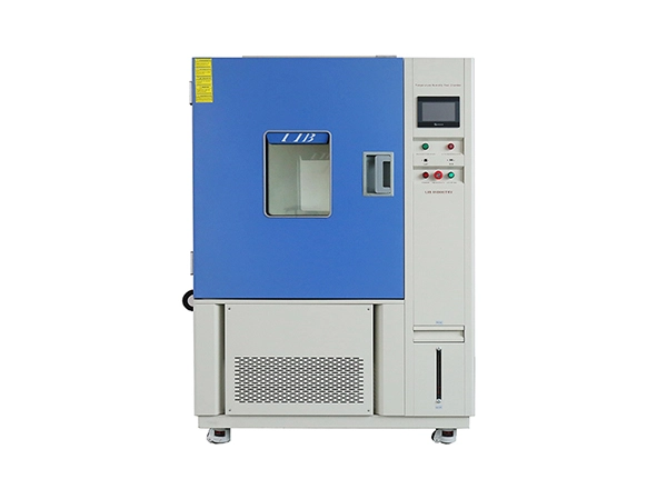
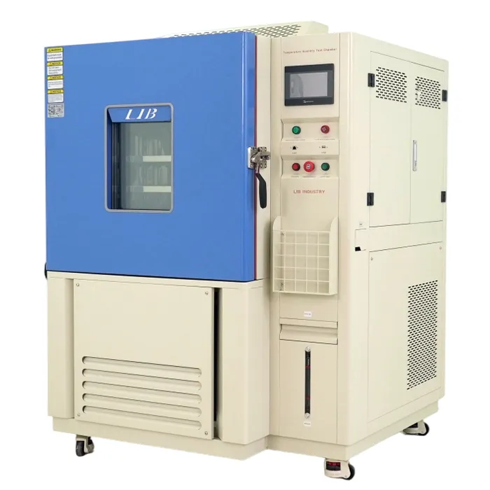
 Environmental test chambers frequently meet catalog specifications when completely empty. However, once test engineers install sample racks, wiring harnesses, structural fixtures, and heavy test units, chamber performance changes dramatically.
The essential engineering question is not merely whether the chamber controller reaches its programmed setpoint, but whether every individual sample receives the required temperature and humidity condition for the full duration of the test.
To guarantee test validity, engineers must perform loaded environmental chamber mapping, evaluate temperature uniformity, measure humidity recovery time, and establish repeatable sample placement.
This comprehensive guide breaks down the engineering principles behind loaded environmental chamber validation, provides step-by-step mapping methodologies, compares equipment selection, and shows how LIB Industry delivers tailored solutions for demanding testing standards.
Empty-chamber factory data serves as a controlled baseline for initial equipment selection and commissioning. However, empty-chamber data cannot guarantee performance under actual laboratory or production loading.
It is vital to distinguish between stability over time and uniformity across space:
· Temperature Stability: Describes short-term temperature fluctuations at a single physical point over time.
· Temperature Uniformity: Describes spatial temperature differences between multiple locations inside the chamber at the exact same moment.
Example: A chamber controller may indicate a stable 40.0°C with only ±0.5°C fluctuation at the center sensor. However, a rear corner might sit at 41.5°C while a shelf near the door drops to 38.8°C. Although the controller looks rock-solid, the actual spatial temperature spread across the usable volume is 2.7°C.
Standard IEC 60068-3-6:2026 consolidates guidance for confirmation of temperature and humidity chambers. While empty-chamber confirmation procedures typically specify at least 9 temperature monitoring points for volumes up to 2,000 L (and 15 points for larger chambers) with a 30-minute observation window, loaded validation requires extending these concepts to accommodate real physical loads.
Relative humidity (RH) is strictly bound to air temperature. A cooler corner naturally exhibits higher RH even if the moisture mass in the air remains uniform.
Furthermore, published catalog specs (e.g., ±2.5% RH deviation) represent empty air volume capabilities. Absorbent materials—such as paper, foam, textiles, or dry cardboard packaging—act as moisture sinks, absorbing or releasing moisture and significantly delaying equilibrium long after the controller claims setpoint recovery.
Evaluation Criteria | Empty Chamber Baseline | Representative Loaded Chamber |
Primary Purpose | Confirm equipment baseline capability & factory specs | Prove fitness for actual product test standards |
Main Influences | Chamber refrigeration, heater, and blower design | Thermal mass, heat dissipation, packing density, and airflow obstruction |
Typical Finding | Inherent thermal gradients near chamber walls/doors | Shifted hot/cold zones, slower recovery, larger thermal gradients |
Acceptance Basis | Equipment catalog parameters or general equipment standards | Specific product testing standards (e.g., ICH Q1A(R2), MIL-STD), protocols, and risk assessments |
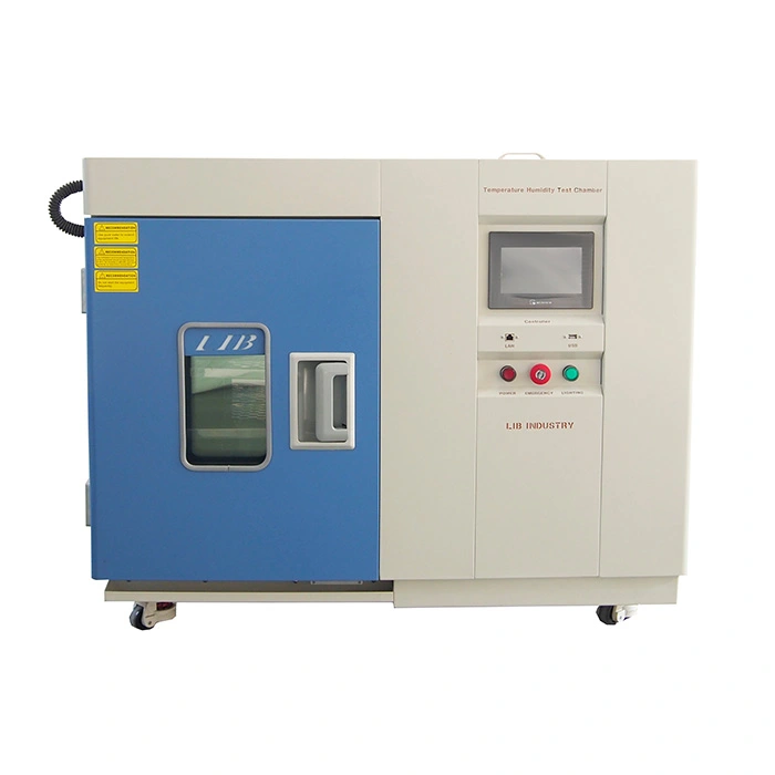
Loading an Temperature Humidity Controlled Environmental Condition Unit fundamentally alters heat transfer mechanics, moisture exchange, and air recirculation pathways.
Different physical loads introduce unique thermodynamic challenges:
· Thermal Mass: Heavy metallic assemblies take significantly longer to reach thermal equilibrium with ambient chamber air.
· Powered Heat Loads: Active electronic components release heat (often hundreds of watts), creating localized thermal plumes that disrupt uniform airflow.
· Air Density & Blockage: Non-powered samples packed tightly together form solid barriers, blocking forced air circulation between supply and return ducts.
Rule of Thumb: Always record sample mass, material composition, exposed surface area, power consumption, and cable feedthrough configurations. For powered test items, map the chamber during the highest operational thermal load.
Never place validation sensors in boundary zones where test samples are forbidden (such as immediately adjacent to supply air vents or heating elements).
· Sensor Quantity: Place calibrated thermocouples or RTDs at all 8 corners of the usable volume, the geometric center, each occupied shelf level, and known high-risk zones (e.g., near door seals, high-density sample blocks, and cable pass-through ports).
· Calibration Uncertainty: For a target tolerance of ±2.0°C, temperature sensors should possess a traceable calibration uncertainty between ±0.2°C and ±0.5°C to ensure adequate decision risk margins.
Humidity recovery time begins when a door opening or sample insertion disturbance ends, and finishes only when all mapped sensors return to and remain inside the acceptable RH range.
[Door Opened / Load Inserted] ──> [Door Closed] ──> [Controller Setpoint Met] ──> [All Sensor Locations Stabilized]
│ │
└────────────── TRUE HUMIDITY RECOVERY TIME ───┘
When validating humidity recovery:
1. Standardize door openings (e.g., 60 seconds at a defined 90-degree opening angle).
2. Measure every mapped point across all shelves. Often, the main chamber controller reports complete recovery in 8 minutes, while sensors behind dense, absorbent test items require 25 minutes or more to reach equilibrium.
3. Record ambient room temperature, ambient RH, peak RH overshoot, and true stabilization time.
Repeatable sample placement is a critical requirement of any defensible test procedure. Changing the spatial arrangement of test items can alter thermal exposure even if the programmed controller profile remains unchanged.
To ensure consistent environmental exposure across routine test runs, implement these clear placement guidelines:
· Clear Circulation Paths: Maintain unobstructed lines of sight between supply air outlets and return grilles.
· Fixed Spacing Gaps: Maintain defined minimum clearances (e.g., 50 mm to 100 mm) between adjacent sample packages and shelf walls.
· Distribute Thermal Loads: Spread powered, heat-generating electronic components across the working volume rather than clustering them on a single shelf.
· Surface Orientation: Position flat, broad sample surfaces parallel to forced air streams to avoid creating air damming effects.
· Visual Documentation: Maintain a photographed loading diagram attached directly to the chamber exterior, specifying exact shelf height indices and sample arrangements.
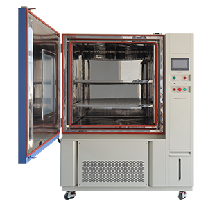
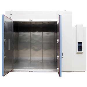
Selecting the correct chamber size and air circulation capacity prevents severe loading bottlenecks. The matrix below compares standard chamber types manufactured by LIB Industry.
Feature / Parameter | Benchtop Temperature & Humidity Chamber | Standard Environmental Chamber | Walk-In Environmental Testing Chamber |
Usable Volume Range | 50 L to 100 L | 100 L to 1,000 L | 2,000 L to 100,000 L+ (Custom) |
Temperature Range | -20℃/−40°C /−70°C to +150°C / +180°C | ||
Humidity Range | 10%/20% to 98% RH | ||
Airflow Mechanism | Compact forced air circulation | High-output centrifugal fan forced airflow | Heavy-duty modular ducted air circulation |
Heat Load Handling | Low (ideal for small non-powered items) | Moderate to High (up to 1,000W active load) | High to Very High (Multi-kW active loads) |
Primary Applications | R&D labs, small PCB testing, medical devices | Component qualification, pharma stability, automotive parts | Whole vehicles, large energy storage systems, pallet loads |
|
|
| |
Established in 2012, LIB Industry has grown into a globally trusted environmental test chamber manufacturer and turnkey solution provider. As specialists in test chamber design and production, LIB Industry delivers standard and highly customized environmental testing equipment tailored to rigorous industrial requirements.
LIB Industry provides an end-to-end service experience designed to simplify equipment acquisition and ensure compliance:
1. Requirement Analysis: In-depth review of product dimensions, thermal mass, heat load, and target test standards.
2. Customized Design: Tailored airflow ducting, port feedthrough configurations, and rack positioning.
3. Precision Manufacturing: High-grade stainless steel interior construction with high-density thermal insulation.
4. Rigorous Quality Control: Every LIB Industry chamber undergoes 72 hours of continuous commissioning and multi-point calibration verification prior to shipping.
5. On-Site Installation & Training: Global field engineers handle delivery, setup, mapping support, and operational training.
To ensure complete peace of mind, LIB Industry backs every test chamber with:
· 3-Year Comprehensive Warranty: Covering major system components, refrigeration units, and controllers.
· Lifetime Service & Support: Access to technical assistance, spare parts availability, and calibration guidance for the entire operational life of the equipment.
· Best For: Space-constrained laboratories testing small electronic components, sensors, or pharmaceutical samples.
· Key Features: Ultra-compact footprint, low noise operation, programmable touchscreen controller, excellent single-point stability within ±0.5°C.
· Best For: Industrial testing requiring compliance with IEC 60068, MIL-STD, or ICH Q1A(R2) stability guidelines under moderate to heavy loading.
· Key Features: High-capacity heating/cooling ramp rates (3°C/min heating, 1°C/min cooling average), uniform forced air distribution, multi-size silicone-sealed feedthrough ports, intuitive data logging via Ethernet/USB.
· Best For: Large-scale industrial assemblies, automotive parts, battery packs, and high-density production batch testing.
· Key Features: Modular panel construction, heavy-duty floor loading capabilities, customizable high-volume ducted airflow to eliminate dead zones around large physical structures, integrated safety systems for active power loads.
A leading automotive electronics supplier experienced intermittent test failures during thermal shock and stability cycling. Although their existing chamber met empty-chamber factory specs (±0.5°C control display), internal quality audits revealed that active electronic control units (ECUs) on lower shelves were running up to 4.2°C warmer than units near the top supply duct, violating their internal testing protocol.
LIB Industry engineers analyzed the customer's sample density, power draw (combining 400 Watts of active heat output), and physical fixture blocking:
1. Customized Airflow Design: LIB Industry re-engineered a 800L Temperature Humidity Chamber featuring a modified rear-plenum forced air distribution system with adjustable louvers.
2. Custom Fixture Racks: Designed perforated wire-mesh shelf racks to maximize vertical airflow around ECU housings.
3. Validation & On-Site Mapping: LIB Industry field technicians installed 15 calibrated sensors throughout the loaded chamber, performing a comprehensive mapping study under full 400W electrical load.
· Temperature Uniformity: Achieved a spatial uniformity of ±1.1°C across all 15 points under full active load (well within the required ±2.0°C limit).
· Humidity Recovery: Reduced door-opening humidity recovery time from 28 minutes down to 9 minutes.
· Certification: The system successfully passed 3rd-party ISO/IEC 17025 calibration on-site, complete with full documentation and operational training provided by LIB Industry.
No. Empty-chamber data provides a baseline for mechanical system capability, but it cannot predict how sample thermal mass, active heat generation, moisture absorption, or physical airflow blockage will alter temperature and humidity distribution during actual testing. A representative loaded mapping study is necessary to verify performance.
To conduct a loaded uniformity test, place calibrated temperature sensors at the 8 corners of the usable working volume, the geometric center, near door seals, and directly adjacent to high-density or heat-generating samples. Run the chamber at target setpoints, allow the system to stabilize, and calculate the maximum temperature minus minimum temperature across all sensors at each timestamp.
First, establish a standard operational disturbance (such as opening the chamber door to a 90-degree angle for 60 seconds). Close the door and measure the time required for every single mapped sensor location—not just the controller display—to return to the target relative humidity tolerance band and remain stable.
While there is no single universal percentage for all applications, standard engineering practices recommend leaving a minimum gap of 50 mm to 100 mm between test samples and chamber walls, avoiding direct contact with metal surfaces, and keeping all air supply vents and return grilles completely clear.
LIB Industry provides an industry-leading 3-Year Comprehensive Warranty on standard environmental chambers, backed by Lifetime Service and Support. Service includes 24/7 technical assistance, spare parts support, and on-site field engineering services for installation, calibration, and training.
Validating an environmental test chamber under actual physical loads transforms a simple temperature box into a fully traceable, defensible testing system. By implementing rigorous loaded mapping protocols, calculating true spatial uniformity, verifying humidity recovery times, and establishing standardized sample placement, engineering teams ensure complete testing reliability.
Whether you need a compact laboratory benchtop unit, a high-performance standard chamber, or a custom walk-in environmental enclosure, LIB Industry delivers the design expertise, custom manufacturing, and global support your application demands.
Ready to optimize your environmental testing accuracy? Contact the expert engineering team at LIB Industry to discuss your testing requirements, request a customized mapping protocol, or receive a competitive product quote.
 English
 русский
 français
 العربية
 Deutsch
 Español
 한국어
한국어 italiano
 tiếng việt
 ไทย
ไทย Indonesia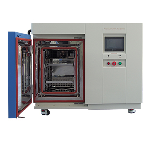
.webp "UVA-340 vs UVB-313: Choosing the Right Lamp for UV Weathering Testing")