Choose a Thermal Shock Chamber when the test requires an almost instantaneous transition between extreme hot and cold environments and the objective is to expose products to severe thermal shock. Choose a Rapid Temperature Change Chamber when temperature must rise and fall at a controlled ramp rate for repeated thermal cycling, fatigue, or environmental stress screening. Both approaches can support standards such as IEC 60068-2-14 and MIL-STD-810, while specific applications may require JESD22, ISO 16750, or other methods. The most important selection factor is the required temperature transition profile: actual switching time for thermal shock versus controlled ramp rate, dwell time, and cycle count for rapid temperature change testing.
Thermal testing evaluates how products respond when temperature changes during operation, storage, transportation, or other real-world conditions.
Typical test samples include semiconductor packages, PCBs, sensors, connectors, automotive electronic modules, battery components, aerospace parts, solar components, plastics, coatings, and composite materials.
The failure mechanisms can be different depending on how quickly the temperature changes.
A thermal shock test creates a severe temperature gradient by rapidly moving the specimen between hot and cold environments. The sudden change can produce differential expansion and contraction between materials. This can reveal cracking, delamination, solder-joint weakness, seal failure, connector problems, and other defects that may not appear during gradual temperature cycling.
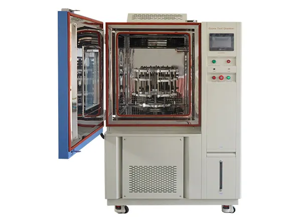
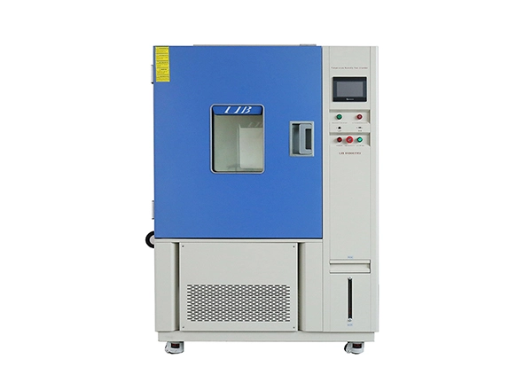
A rapid temperature change chamber, by comparison, changes the temperature of the chamber at a specified rate. LIB's Fast Change Rate Chamber can achieve a typical change rate of 5°C/min, while its rapid-rate thermal cycling configurations support 5°C/min, 10°C/min, 15°C/min, or higher depending on the model and customization.
This distinction is important. Thermal shock concentrates on abrupt thermal exposure, while rapid temperature change testing focuses on repeatable controlled transitions.
For example, an electronic assembly may survive hundreds of controlled cycles but fail when exposed to a sudden transfer from a hot zone to a cold zone. Conversely, a product designed for years of daily temperature changes may need hundreds or thousands of controlled cycles to evaluate cumulative thermal fatigue.
The exact test profile must be determined from the applicable standard and product qualification plan. Common methods include:
Standard / Test Method | Temperature | Humidity | Typical Cycle / Duration | Spray / Pressure |
IEC 60068-2-14 | Low/high temperatures according to test method | N/A | Repeated temperature changes | N/A |
MIL-STD-810 Method 503 | Extreme high/low temperature transitions | N/A | Defined thermal shock cycles | N/A |
JESD22-A104 | Semiconductor-specific temperature cycling | N/A | Repeated low/high temperature exposure | N/A |
ISO 16750-4 | Automotive climatic loads | Application dependent | Temperature cycling and endurance profiles | Application dependent |
IEC 61215 | Solar module environmental testing | Application dependent | Defined thermal cycling sequence | Application dependent |
ASTM D4169 | Distribution and package performance | Application dependent | Defined conditioning cycles | Mechanical/environmental stresses |
LIB identifies IEC 61215, IEC 61646, IEC 61108, IEC 62688, AAMA501, ASTM D4169-16, and MIL-STD-811D among the standards supported by its thermal-cycle and fast-change-rate chamber configurations.
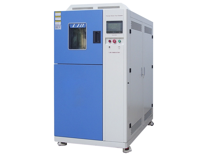
For thermal shock, LIB's Temperature Shock Test Chamber provides hot and cold zones and can move specimens between them within approximately three seconds. The listed models range from 22 L to 505 L, with upper hot-zone temperatures reaching +220°C and low-temperature capability down to approximately -75°C, depending on configuration.
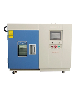
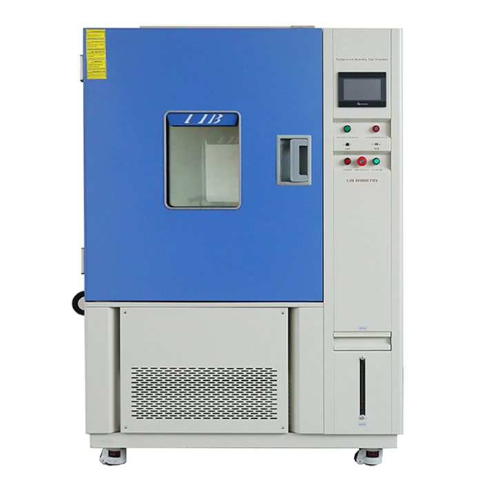
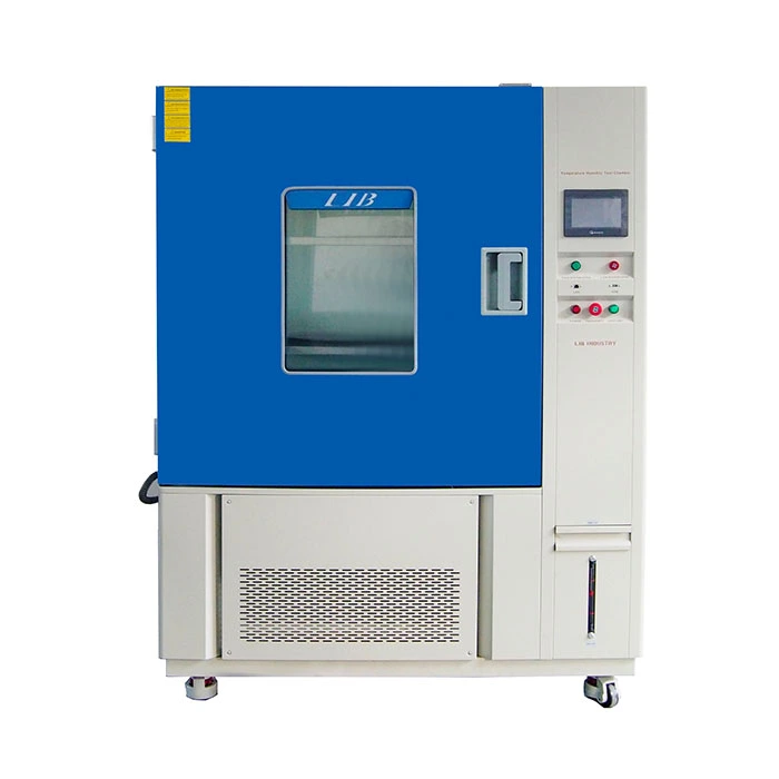
For controlled thermal cycling, LIB's Temperature Cycle Chamber offers 100 L to 1,000 L models, with temperature options extending from -20°C, -40°C, or -70°C to +150°C and configurable heating and cooling rates.
Parameter | Thermal Shock Chamber | Rapid Temperature Change / Thermal Cycling Chamber |
Temperature range | Typically around -75°C to +220°C, model dependent | Typically -20/-40/-70°C to +150°C |
Humidity range | Normally not the primary function | Optional humidity system on selected models |
Chamber volume | Approximately 22–505 L on listed shock models | Approximately 100–1,000 L standard models |
Ramp rate | Very rapid zone-to-zone transition; sample transfer can occur within seconds | Typically 5–15°C/min, with higher rates available on selected/custom models |
Airflow | Independent circulation in hot and cold zones | Forced air circulation through one workroom |
Sample heat load | Must be considered for rapid recovery after transfer | Must be considered for maintaining the programmed ramp rate |
Safety configuration | Over-temperature, refrigeration, electrical and transfer-system protection | Over-temperature, electrical and refrigeration protection |
Applicable standards | IEC 60068-2-14, MIL-STD methods, JESD and application-specific methods | IEC 60068, JESD22, IEC 61215, ASTM and other cycling methods |
The physical operating principle is the clearest difference.
LIB's Thermal Shock Chamber uses separate hot and cold environments. In a two-zone configuration, an automated basket transfers the specimen between the zones. A three-zone configuration uses a dedicated test area with hot and cold air circuits. This allows the sample to experience an extremely rapid temperature transition.
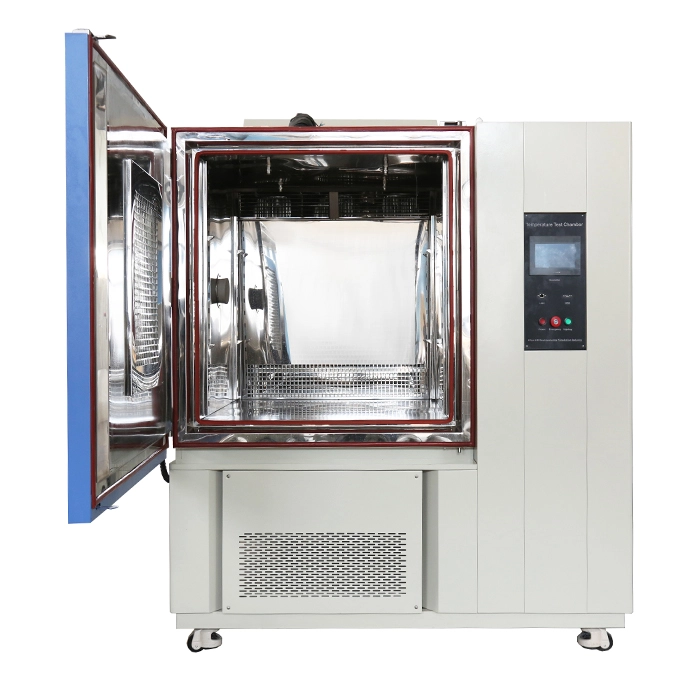
The Temperature Cycle Chamber instead controls the temperature of a single test workspace according to a programmed profile. Heating and cooling rates can be selected according to the required test condition, making the system more suitable for repeated thermal cycling and controlled thermal fatigue studies.
Therefore, a chamber with a high ramp rate should not automatically be considered equivalent to a thermal shock chamber. The test mechanism, specimen exposure, transition time, and applicable standard all need to match.
A chamber changing at 15°C/min is not necessarily performing the same test as a thermal shock chamber that transfers a sample between hot and cold zones within seconds. These are different test mechanisms.
Engineers should first determine the high and low temperatures, transition requirement, dwell time, number of cycles, and sample response before selecting equipment.
Large metal assemblies or battery modules can significantly affect recovery time. The chamber specification should be evaluated under the actual sample heat load rather than empty-chamber conditions.
A faster temperature change is not automatically better. If the actual qualification profile requires a controlled rate, excessive ramping may introduce unrealistic stress and produce non-representative failures.
Poor specimen placement can create temperature gradients and affect repeatability. Adequate clearance around the sample is necessary for effective air circulation.
Electrical testing may require power cables, thermocouples, communication wires, or monitoring equipment. These should be considered before finalizing the chamber configuration.
Two chambers may both reach -70°C and +150°C but provide completely different transition performance. Temperature range, ramp rate, switching method, dwell stability, and cycle capability should be evaluated together.
The correct chamber depends on the stress profile rather than simply the desired temperature range.
Benchtop: Suitable for small components and laboratory samples when the required test profile can be achieved within a compact working volume.
Reach-In: Appropriate for larger specimens or multiple samples requiring greater workspace while still using controlled temperature cycling.
Walk-In: Better suited to large assemblies, vehicle components, battery systems, or high-volume test programs that exceed standard chamber dimensions.
Thermal Shock: Recommended when the qualification requires an abrupt transition between hot and cold environments. LIB offers two-zone and three-zone configurations, including basket-transfer and air-circuit switching designs.
Salt Spray: Appropriate when corrosion rather than thermal stress is the primary failure mechanism.
IP: Suitable when the product must be evaluated for resistance to dust or water ingress.
Special Custom Chamber: Appropriate when thermal cycling must be combined with humidity, vibration, pressure, gas, battery safety, or other environmental stresses.
LIB's Thermal Chambers range includes Thermal Shock Chambers, Temperature Cycle Chambers, Rapid Rate Thermal Cycling Chambers, High and Low Temperature Impact Test Chambers, and other configurations for different thermal stress profiles.
For controlled repeated cycling, the LIB Temperature Cycle Chamber provides 100 L–1,000 L configurations and programmable temperature rates. For sudden high-to-low transitions, the LIB Temperature Shock Test Chamber provides dedicated hot and cold zones and rapid specimen transfer.
The choice is also strongly influenced by the application. LIB's Environmental Test Chamber for Electronics identifies thermal cycling and thermal shock as important methods for evaluating PCBs, electronic components, and automotive electronics. Rapid thermal changes can reveal mechanical and electrical failures that may remain hidden under steady-temperature testing.
For a more detailed explanation of the underlying test methods, LIB's article What Is the Difference Between Thermal Cycling Test and Thermal Shock Test? compares gradual temperature cycling with sudden thermal shock and discusses their different test objectives, temperature-change rates, and applications.
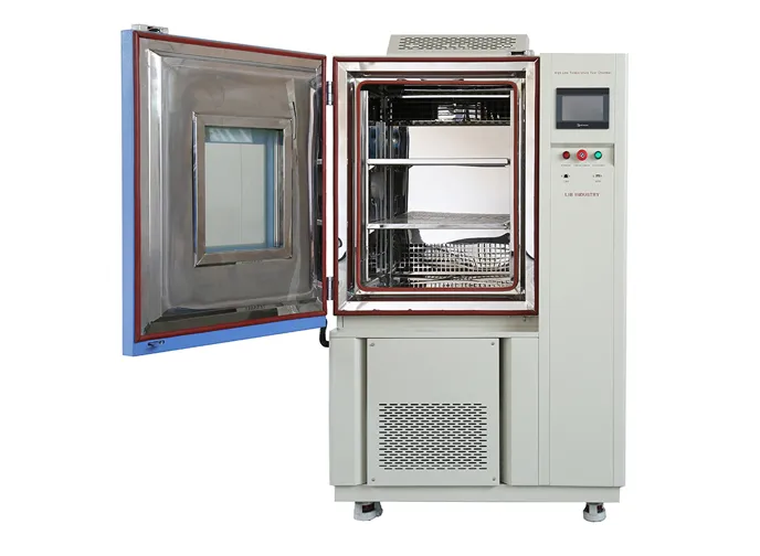
Thermal shock exposes a specimen to an abrupt temperature transition, typically by moving it between hot and cold zones. Rapid temperature change testing controls the heating and cooling rate within a chamber and repeats the programmed temperature profile.
A thermal cycling chamber is generally more suitable when the objective is to reproduce repeated expansion and contraction over many controlled cycles. Thermal shock can be selected when sudden temperature transitions are specifically required by the test method.
No. A 15°C/min ramp describes the rate at which chamber temperature changes. A thermal shock chamber normally creates a much more abrupt specimen temperature transition by switching between separate thermal zones.
There is no universal number. The required cycle count depends on the applicable standard, product specification, qualification level, and failure mechanism being investigated.
Some advanced configurations can support multiple thermal test functions, but a conventional rapid-rate thermal cycling chamber should not automatically be considered a replacement for a dedicated thermal shock system. The required switching mechanism and standard should be confirmed first.
Select the smallest working volume that safely accommodates the sample, fixture, sensors, and required airflow clearance. LIB's thermal shock models range from compact units to larger configurations, allowing the chamber to be matched to specimen dimensions and loading requirements.
An RFQ should include high and low temperature limits, transition or ramp rate, dwell time, cycle count, sample dimensions and weight, heat load, required standard, fixture requirements, cable ports, power supply, and any humidity or special environmental functions.
It is preferable when engineers need repeatable controlled ramps, multiple temperature cycles, thermal fatigue evaluation, accelerated stress screening, or long-duration cycling rather than an instantaneous hot-to-cold transfer.
 English
 русский
 français
 العربية
 Deutsch
 Español
 한국어
한국어 italiano
 tiếng việt
 ไทย
ไทย Indonesia